
Overview
In this article, we will learn about the interfacing of Soil NPK Sensor Sensor with Arduino & make our own Arduino Soil NPK Meter. The soil nutrient content can be easily measured using NPK Soil Sensor & Arduino. Measurement of soil content N (nitrogen), P (phosphorus), and K (potassium) is necessary to determine how much additional nutrient content is to be added to soil to increase crop fertility.
The soil fertility is detected using NPK sensors. A major component of soil fertilizer is nitrogen, phosphorus, and potassium. The knowledge of the soil nutrient concentration can help us to learn about nutritional deficiency or abundance in soils used to endorse plant production.
There are multiple methods of measuring the soil nutrient content like using some optical sensors or using the spectrometer. But the spectral analysis method is not convenient and the drawback is the data are only 60-70% correct. While comparing the spectral analysis method with traditional wet chemistry methods, the accuracy of the products is yet to be fully resolved, given the paucity of data in that regard.
So, here we will use a JXCT Soil NPK Sensor to detect the soil nitrogen, phosphorous & Potassium in a soil. The JXCT Soil NPK sensor is a low cost, quick responsive, high precision & portable Sensor that works with Modbus RS485. The advantage of this sensor over a traditional detection method is that it gives very fast measurement & data are highly accurate. All you need is to insert its probe in soil and get the reading using Arduino . So, let’s learn in detail about the interfacing of Soil NPK Sensor Sensor with Arduino.
Bill of Materials
The components required for making a device that can help you in studying the Soil Nutrient Content is given below. You can purchase almost all the components from Amazon.
| S.N. | Components Name | Quantity | Purchase Link |
|---|---|---|---|
| 1 | Arduino Nano Board | 1 | RoboticsDnA.in |
| 2 | NPK Sensor | 1 | RoboticsDnA.in |
| 3 | 0.96″ OLED Display | 1 | RoboticsDnA.in |
| 4 | MAX485 Modbus Module | 1 | RoboticsDnA.in |
| 5 | 9-12V DC Power Supply | 1 | RoboticsDnA.in |
| 6 | Connecting Wires | 10 | RoboticsDnA.in |
| 7 | Breadboard | 1 | RoboticsDnA.in |
Soil NPK Sensor
The soil NPK sensor is suitable for detecting the content of nitrogen, phosphorus, and potassium in the soil. It helps in determining the fertility of the soil thereby facilitating the systematic assessment of the soil condition. The sensor can be buried in the soil for a long time. It has a High-quality probe, rust resistance, electrolytic resistance, salt & alkali corrosion resistance, to ensure the long-term operation of the probe part. Therefore, it is suitable for all kinds of soil. It is suitable for the detection of alkaline soil, acid soil, substrate soil, seedling bed soil & coconut bran soil.

The sensor doesn’t require any chemical reagent. Since it has High measurement accuracy, fast response speed, and good interchangeability, it can be used with any microcontroller. You cannot use the sensor directly with the microcontroller as it has a Modbus Communication port. Hence you need any Modbus Module like RS485/MAX485 and connect the sensor to the microcontroller.
The sensor operates on 9-24V & power consumption is very low. While talking about the accuracy of the sensor, it is up to within 2%. The nitrogen, phosphorous & potassium measuring resolution is up to 1mg/kg (mg/l).

Using this Soil NPK Sensor Sensor , you can make your own Arduino Soil NPK Meter or any Cloud IoT Based Soil Nutrient Content Monitoring System.
Specifications
1. Power: 9V-24V
2. Measuring Range: 0-1999 mg/kg (mg/l)
3. Operating Temperature: 5-45 °C
4. Resolution: 1mg/kg
5. Precision: ±2% F.S.
6. Output Signal: RS485
7. Baud Rate: 2400/4800/9600
8. Protection Class: IP68
MAX485 TTL to RS-485 Interface Module
The MAX485 TTL to RS-485 Interface Module allows us to use the RS-485 differential signaling for robust long-distance serial communications up to 1200 meters or in electrically noisy environments and is commonly used in industrial environments. It supports up to 2.5MBit/Sec data rates, but as distance goes up, the maximum data rate that can be supported comes down.

The data starts out as a typical TTL level serial as far as the microcontroller is concerned while the RS-485 module takes care of converting the electrical signals between TTL and the differential signaling used by RS-485. A significant benefit of RS-485 is that it supports multiple devices (up to 32) on the same cable, commonly referred to as ‘multi-drop’.
Specifications
1. Use MAX485 Interface chip
2. Uses differential signaling for noise immunity
3. Distances up to 1200 meters
4. Speeds up to 2.5Mbit/Sec
5. Multi-drop supports up to 32 devices on same bus
6. Red power LED
7. 5V operation
Pinout & Module Connection
The module has two 4-pin headers on the assembly.
1 x 4 Header (Data side)
RO = Receiver Output. Connects to a serial RX pin on the microcontroller
RE = Receiver Enable. Active LOW. Connects to a digital output pin on a microcontroller. Drive LOW to enable receiver, HIGH to enable Driver
DE = Driver Enable. Active HIGH. Typically jumpered to RE Pin.
DI = Driver Input. Connects to serial TX pin on the microcontroller
1 x 4 Header (Output side)
VCC = 5V
B = Data ‘B’ Inverted Line. Common with the B
A = Data ‘A’ Non-Inverted Line. Connects to A on far end module
GND = Ground
1 x 2 Screw Terminal Block (Output side)
B = Data ‘B’ Inverted Line. Connects to B on far end module
A = Data ‘A’ Non-Inverted Line. Connects to A on far end module
Interfacing Soil NPK Sensor Sensor with Arduino
Now, let us interface the Soil NPK Sensor Sensor with the Arduino Nano Board using the MAX485 Modbus Module. Check the connection diagram below.

Connect the R0 & DI pin of from the Modbus to D2 & D3 Arduino using Software Serial. Similarly, we have to enable DE & RE high. To do this connect the DE & RE Pins to the D7 & D8 pin of Arduino. The NPK Sensor has 4 wires. The brown one is VCC which needs a 9V-24V Power Supply. The GND pin which is black in color. So connect it to the GND of Arduino . The Blue wire which is the B pin is connected to the B pin of MAX485 & the Yellow Wire which is the A pin is connected to the A pin of MAX485.

The 0.96″ SSD1306 OLED Display is an I2C Module. Connect the OLED Display VCC & GND pins to 3.3V & GND of Arduino . Similarly, connect its SDA & SCL pins to the A4 & A5 of Arduino. You can follow the circuit diagram & assemble the circuit on a breadboard or make a custom PCB.

Modbus Command for NPK Sensor
Modbus commands can instruct a Modbus Device to:
1. change the value in one of its registers, which is written to Coil and Holding registers
2. read an I/O port: Read data from Discrete and Coil ports,
3. command the device to send back one or more values contained in its Coil and Holding register
A Modbus command contains the Modbus address of the device it is intended for (1 to 247). The Modbus address is also called an inquiry frame. Only the addressed device will respond and act on the command, even though other devices might receive it.
The NPK Sensor has 3 different inquiry frame for reading the value of Nitrogen (N), Phosphorous (P) & Potassium (K). The inquiry frame is provided along with the instruction manual. For the NPK data the following individual inquiry frameworks:
1. Nitrogen: {0x01,0x03, 0x00, 0x1e, 0x00, 0x01, 0xe4, 0x0c}

The inquiry frame for getting Soil Nitrogen Value is:

You will get the following as a response:
You can calculate the Soil Nitrogen from the Response you receive. For example, if you get 0030 as a response then Soil Nitrogen Value will be:
0020 H(hexadecimal) = 32 (Decimal) => Nitrogen = 32mg/kg
2. Phosphorous:{0x01,0x03, 0x00, 0x1f, 0x00, 0x01, 0xb5, 0xcc}

The inquiry frame for getting Soil Phosphorous Value is:

You will get the following as a response:
You can calculate the Soil Phosphorous from the Response you receive. For example, if you get 0030 as a response then Soil Nitrogen Value will be:
0025 H(hexadecimal) = 37 (Decimal) => Phosphorous = 37/kg
3. Potassium:{0x01,0x03, 0x00, 0x20, 0x00, 0x01, 0x85, 0xc0}

The inquiry frame for getting Soil Potassium Value is:

You will get the following as a response:
You can calculate the Soil Potassium from the Response you receive. For example, if you get 0030 as a response then Soil Potassium Value will be:
0030 H(hexadecimal) =48 (Decimal) => Potassium = 48mg/kg
Source Code/Program
The source code for interfacing Soil NPK Sensor Sensor with Arduino & retrieving Soil Nutrient value from the Sensor via Modbus command is given below. You can send the command and retrieve the value in HEX Code. The HEX code needs to be converted into Decimal to get the Measured Soil Nutrient content data.
Since we are using OLED Display to display the Soil Nutrient values (Nitrogen, Phosphorous & Potassium) in mg/kg, you will need OLED Library. Download the following OLED Library and add it to the Arduino IDE.
1. Adafruit SSD1306 Library: Download
2. Adafruit GFX Library: Download
Here is the complete source code. Compile the code & upload it to the Arduino Nano Board.
#include <SoftwareSerial.h>
#include <Wire.h>
#include <Adafruit_GFX.h>
#include <Adafruit_SSD1306.h>

#define SCREEN_WIDTH 128    // OLED display width, in pixels
#define SCREEN_HEIGHT 64    // OLED display height, in pixels
#define OLED_RESET -1       // Reset pin # (or -1 if sharing Arduino  reset pin)
Adafruit_SSD1306 display(SCREEN_WIDTH, SCREEN_HEIGHT, &Wire, OLED_RESET);

#define RE 8
#define DE 7

//const byte code[]= {0x01, 0x03, 0x00, 0x1e, 0x00, 0x03, 0x65, 0xCD};
const byte nitro[] = {0x01,0x03, 0x00, 0x1e, 0x00, 0x01, 0xe4, 0x0c};
const byte phos[] = {0x01,0x03, 0x00, 0x1f, 0x00, 0x01, 0xb5, 0xcc};
const byte pota[] = {0x01,0x03, 0x00, 0x20, 0x00, 0x01, 0x85, 0xc0};

byte values[11];
SoftwareSerial mod(2,3);

void setup() {
  Serial.begin(9600);
  mod.begin(9600);
  pinMode(RE, OUTPUT);
  pinMode(DE, OUTPUT);

  display.begin(SSD1306_SWITCHCAPVCC, 0x3C); //initialize with the I2C addr 0x3C (128x64)
  delay(500);
  display.clearDisplay();
  display.setCursor(25, 15);
  display.setTextSize(1);
  display.setTextColor(WHITE);
  display.println(" NPK Sensor ");
  display.setCursor(25, 35);
  display.setTextSize(1);
  display.print("Initializing");
  display.display();
  delay(3000);
}

void loop() {
  byte val1,val2,val3;
  val1 = nitrogen();
  delay(250);
  val2 = phosphorous();
  delay(250);
  val3 = potassium();
  delay(250);


  Serial.print("Nitrogen: ");
  Serial.print(val1);
  Serial.println(" mg/kg");
  Serial.print("Phosphorous: ");
  Serial.print(val2);
  Serial.println(" mg/kg");
  Serial.print("Potassium: ");
  Serial.print(val3);
  Serial.println(" mg/kg");
  delay(2000);

  display.clearDisplay();


  display.setTextSize(2);
  display.setCursor(0, 5);
  display.print("N: ");
  display.print(val1);
  display.setTextSize(1);
  display.print(" mg/kg");

  display.setTextSize(2);
  display.setCursor(0, 25);
  display.print("P: ");
  display.print(val2);
  display.setTextSize(1);
  display.print(" mg/kg");

  display.setTextSize(2);
  display.setCursor(0, 45);
  display.print("K: ");
  display.print(val3);
  display.setTextSize(1);
  display.print(" mg/kg");

  display.display();
}

byte nitrogen(){
  digitalWrite(DE,HIGH);
  digitalWrite(RE,HIGH);
  delay(10);
  if(mod.write(nitro,sizeof(nitro))==8){
    digitalWrite(DE,LOW);
    digitalWrite(RE,LOW);
    for(byte i=0;i<7;i++){
    //Serial.print(mod.read(),HEX);
    values[i] = mod.read();
    Serial.print(values[i],HEX);
    }
    Serial.println();
  }
  return values[4];
}

byte phosphorous(){
  digitalWrite(DE,HIGH);
  digitalWrite(RE,HIGH);
  delay(10);
  if(mod.write(phos,sizeof(phos))==8){
    digitalWrite(DE,LOW);
    digitalWrite(RE,LOW);
    for(byte i=0;i<7;i++){
    //Serial.print(mod.read(),HEX);
    values[i] = mod.read();
    Serial.print(values[i],HEX);
    }
    Serial.println();
  }
  return values[4];
}

byte potassium(){
  digitalWrite(DE,HIGH);
  digitalWrite(RE,HIGH);
  delay(10);
  if(mod.write(pota,sizeof(pota))==8){
    digitalWrite(DE,LOW);
    digitalWrite(RE,LOW);
    for(byte i=0;i<7;i++){
    //Serial.print(mod.read(),HEX);
    values[i] = mod.read();
    Serial.print(values[i],HEX);
    }
    Serial.println();
  }
  return values[4];
}
Code Explanation
This Arduino code is designed to interact with an NPK (Nitrogen, Phosphorus, and Potassium) sensor, which are typically used to measure the levels of these nutrients in soil. This information is then displayed on an OLED screen.
| 123456789101112 | #include <SoftwareSerial.h>#include <Wire.h>#include <Adafruit_GFX.h>#include <Adafruit_SSD1306.h>#define SCREEN_WIDTH 128 // OLED display width, in pixels#define SCREEN_HEIGHT 64 // OLED display height, in pixels#define OLED_RESET -1 // Reset pin # (or -1 if sharing Arduino reset pin)Adafruit_SSD1306 display(SCREEN_WIDTH, SCREEN_HEIGHT, &Wire, OLED_RESET);#define RE 8#define DE 7 |
This section includes necessary libraries for serial communication, I2C communication, and functionality for the OLED display. It also defines certain parameters such as screen width and height for the OLED display, pin number for reset, and pin numbers for the RE (Receive Enable) and DE (Driver Enable) pins used in RS485 communication.
| 123456 | const byte nitro[] = {0x01,0x03, 0x00, 0x1e, 0x00, 0x01, 0xe4, 0x0c};const byte phos[] = {0x01,0x03, 0x00, 0x1f, 0x00, 0x01, 0xb5, 0xcc};const byte pota[] = {0x01,0x03, 0x00, 0x20, 0x00, 0x01, 0x85, 0xc0};byte values[11];SoftwareSerial mod(2,3); |
This part of the code declares and initializes arrays to contain byte sequences for requesting Nitrogen, Phosphorous, and Potassium readings from the sensor. It also initializes a byte array to hold response values, and a software serial interface on pins 2 and 3.
| 12345678 | void setup() { Serial.begin(9600); mod.begin(9600); pinMode(RE, OUTPUT); pinMode(DE, OUTPUT); //… OLED display initialization and message…} |
The setup function initializes the hardware serial port and software serial port at a baud rate of 9600. It also sets the RE and DE pins as outputs. It initializes the OLED display and shows a message.
| 1234567 | void loop() { byte val1,val2,val3; val1 = nitrogen(); val2 = phosphorous(); val3 = potassium(); //… Print values to the serial monitor and OLED display…} |
This is the main loop where it continually requests and retrieves Nitrogen, Phosphorous, and Potassium values from the sensor using the respective functions. It then prints these values to the serial monitor and updates the OLED display with these values.
| 123456789 | byte nitrogen(){ //… Send request, read response, return value…}byte phosphorous(){ //… Send request, read response, return value…}byte potassium(){ //… Send request, read response, return value…} |
These are the functions that handle sending the request byte sequences to the sensor and reading the response. They return the sensor reading values. In each function, it first sets the DE and RE pins high, indicating that it wants to write to the bus. Then it sends the request byte sequence for the respective nutrient. After sending, it sets DE and RE low, indicating that it wants to read from the bus. It then reads the response from the sensor into the ‘values’ array and returns the value of interest.
Note: The code is the only capable of measuring the Soil NPK values up to 255mg/kg. This is because we are only reading 8bit value. According to the datasheet of the Sensor , you can measure the value up to 1999mg/kg. To read such value we have to read 16bit data. Refer to the Soil EC Sensor Code to read such high values.
Monitoring Soil NPK Data on OLED Display
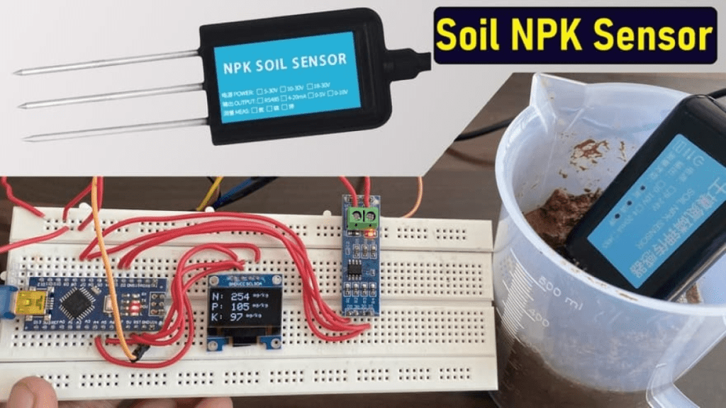
Once you upload the code to Arduino Nano Board, the OLED will initialize along with the sensor. The sensor will take some time for stability and the reading may be incorrect initially.
Once the sensor gets becomes stable, you can dip the sensor in the soil to get the NPK Reading. The volume of Nitrogen, Phosphorous & Potassium which are the Ammonium content in the soil will be displayed as mg/Kg.

So this is how you interface Soil Nutrient Sensor Arduino & get the NPK Readings. Similarly, put the sensor in different samples of soil. You will see a variation in the volume of NPK depending upon the type of soil.

Video Tutorial & Guide
Follow the following video to learn about the entire project & code information.
DIY Soil NPK Meter || Measure Soil Nutrient Content using Soil NPK Sensor Sensor & Arduino
Apart from measuring Soil NPK, you can also measure Soil Moisture Content using Soil Moisture Sensor, Soil Ph using Soil Ph Sensor & Soil EC & Salinity using Soil EC Sensor, which is explained in my one the previous post.
Thus, you can make your own Arduino Soil NPK Meter using the above guide & determine the fertility of the soil. You can also check the advanced version of this project. In the advance version, you can combine Soil NPK Sensor , Temperature Sensor & Soil Moisture Sensor with Arduino: IoT Based Soil Nutrient Monitoring.