
IoT Biometric Fingerprint Attendance System using ESP8266

Overview
In this project IoT Biometric Project, we will learn how to build IoT based Biometric Fingerprint Attendance System using NodeMCU ESP8266 12E, 0.96” OLED Display & R305 Fingerprint Sensor. The ESP8266 Wi-Fi Module will collect the fingerprint data from multiple users and sends it over the internet to a website. The Enrolment of fingerprints is done on the Server using R305 or R307 or any other compatible Fingerprint Sensor and verification is done on the client with the transmission of fingerprint templates over the network.
The website that is coded in PHP has a database and records of attendance. By logging into the website, you can collect all the attendance records of each user including personal details as well as incoming & outgoing timing. The data can also be downloaded and exported to an excel sheet.

Conventional authentication technologies like RFID tags and authentication cards have a lot of weaknesses, the biometric method of authentication is a prompt replacement for this. Biometrics such as fingerprints, voices and ECG signals are unique human characters that cannot be tampered or replicated. This facilitates real-time system implementations. Biometric Attendance systems are commonly used systems to mark the presence in offices and schools as well as in Biometric Security Lock. This project has a wide application in schools, colleges, business organizations, offices where marking of attendance is required accurately with time. Thus, by using the fingerprint sensor, the system will become more secure for the users.
ill of Materials
The following are the components required to make IoT Based Biometric Fingerprint Attendance System. All the components can be purchased from Amazon. The purchase links are given below.
| S.N. | Components | Quantity | Purchase Links |
|---|---|---|---|
| 1 | NodeMCU ESP8266 Board | 1 | RoboticsDnA.in |
| 2 | R305/R307 Fingerprint Sensor | 1 | RoboticsDnA.in |
| 3 | 0.96″ I2C OLED Display | 1 | RoboticsDnA.in |
| 4 | Connecting Wires | 10 | RoboticsDnA.in |
| 5 | Breadboard | 1 | RoboticsDnA.in |
R305 Fingerprint Scanner Sensor Module
Introduction
This is a finger print sensor module with TTL UART interface for direct connections to microcontroller UART or to PC through MAX232 / USB-Serial adapter. The user can store the finger print data in the module and can configure it in 1:1 or 1: N mode for identifying the person.

The Fingerprint module can be directly interfaced with any microcontroller as well as Arduino Board. This optical biometric fingerprint reader with great features and can be embedded into a variety of end products like access control systems, attendance systems, safety deposit boxes, car door locking systems.
Features
1. Integrated image collecting and algorithm chip together, ALL-in-One
2. The fingerprint reader can conduct secondary development, can be embedded into a variety of end products
3. Low power consumption, low cost, small size, excellent performance
4. Professional optical technology, precise module manufacturing techniques
5. Good image processing capabilities can successfully capture image up to resolution 500 dpi
Specification
1. Fingerprint sensor type: Optical
2. Sensor Life: 100 million times
3. Static indicators: 15KVBacklight: bright green
4. Interface: USB1.1/UART(TTL logical level)
5. RS232 communication baud rate: 4800BPS~115200BPS changeable
6. Dimension: 553221.5mm
7. Image Capture Surface 15—18(mm)
8. Verification Speed: 0.3 sec
9. Scanning Speed: 0.5 sec
10. Character file size: 256 bytes
11. Template size: 512 bytes
12. Storage capacity: 250
13. Security level: 5 (1,2,3,4,5(highest))
14. False Acceptance Rate (FAR) :0.0001%
15. False Rejection Rate (FRR): 0.1%
16. Resolution 500 DPI
17. Voltage :3.6-6.0 VDC
18. Working current: Typical 90 mA, Peak 150mA
19. Matching Method: 1: N
20. Operating Environment Temperature: -20 to 45° centigrades
0.96″ I2C OLED Display
This is a 0.96 inch blue OLED display module. The display module can be interfaced with any microcontroller using SPI/IIC protocols. It is having a resolution of 128×64. The package includes display board, display,4 pin male header pre-soldered to board.

OLED (Organic Light-Emitting Diode) is a self light-emitting technology composed of a thin, multi-layered organic film placed between an anode and cathode. In contrast to LCD technology, OLED does not require a backlight. OLED possesses high application potential for virtually all types of displays and is regarded as the ultimate technology for the next generation of flat-panel displays.
Circuit Diagram: IOT Based Biometric Fingerprint Attendance System

The above circuit diagram shows how an OLED Display & Fingerprint Sensor is interfaced with NodeMCU ESP8266 12E Board. The I2C pins of OLED Display, i.e SDA & SCL are connected to NodeMCU D2 & D1 pins respectively. Similarly, the fingerprint sensor is connected to UART pins D5 & D6. The fingerprint sensor Tx and Rx wire’s color may vary. In my case, the color is yellow and blue where yellow is Tx and Blue is Rx. So connect it by finding appropriate color wires else the module won’t be detected by NodeMCU.
The R305 fingerprint sensor is supplied with 5V through Vin pins of NodeMCU. In my case, the sensor didn’t work at 3.3V. Similarly, connect OLED Vcc pin to 3.3V of NodeMCU.
Setting Up the Website
Here we can set up a website if you have a website and a server. In case you don’t wanna spend money on website management, then you can use your computer IP as a server to store the data locally in localhost.

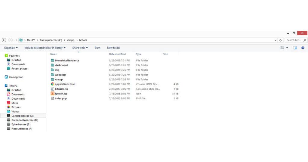
First Download and install Xampp from the link here: Download XAMPP
Once the download and installation is completed copy the following folder:Biometricattendance Folder to C:\xampp\htdocs. This is the location of the website in your C drive.
The website setting process is a little long which is explained in the video below: You can follow the video to completely set up the website.
Source Code/Program
Below is the source code for IoT Based Biometric Fingerprint Attendance System. The code credit goes to original author of the code: Electronics Tech YouTube Channel
Make Sure to change the wifi username and password from this line below:
/* Set these to your desired credentials. */
const char *ssid = "SSID";  //ENTER YOUR WIFI SETTINGS
const char *password = "password";
Also, change the IP Address if you are using Xampp or change the website server if you are on real website from the line below:
String link = "http://YourComputerIP/biometricattendance/getdata.php"; //computer IP or the server domain
Add the following libraries via library manager or simply by adding the following zip files:
1. OLED GFX Library: Download
2. SSD1306 Library: Download
3. Adafruit Fingerprint Sensor Library: Download
//Code Credit to orginal Author: https://www.youtube.com/ElectronicsTechHaIs
//This code created by Electronics Tech channel
//*******************************libraries********************************
#include <SPI.h>
#include <Wire.h>
#include <WiFiClient.h>
#include <ESP8266WiFi.h>
#include <SoftwareSerial.h>
#include <ESP8266WebServer.h>
#include <ESP8266HTTPClient.h>
#include <Adafruit_GFX.h> //https://github.com/adafruit/Adafruit-GFX-Library
#include <Adafruit_SSD1306.h> //https://github.com/adafruit/Adafruit_SSD1306
#include <Adafruit_Fingerprint.h> //https://github.com/adafruit/Adafruit-Fingerprint-Sensor-Library
//************************************************************************
//Fingerprint scanner Pins
#define Finger_Rx 14 //D5
#define Finger_Tx 12 //D6
// Declaration for SSD1306 display connected using software I2C
#define SCREEN_WIDTH 128 // OLED display width, in pixels
#define SCREEN_HEIGHT 64 // OLED display height, in pixels
#define OLED_RESET 0 // Reset pin # (or -1 if sharing Arduino reset pin)
Adafruit_SSD1306 display(SCREEN_WIDTH, SCREEN_HEIGHT, &Wire, OLED_RESET);
//************************************************************************
SoftwareSerial mySerial(Finger_Rx, Finger_Tx);
Adafruit_Fingerprint finger = Adafruit_Fingerprint(&mySerial);
//************************************************************************
/* Set these to your desired credentials. */
const char *ssid = "SSID"; //ENTER YOUR WIFI SETTINGS
const char *password = "password";
//************************************************************************
String postData ; // post array that will be send to the website
String link = "http://YourComputerIP/biometricattendance/getdata.php"; //computer IP or the server domain
int FingerID = 0; // The Fingerprint ID from the scanner
uint8_t id;
//*************************Biometric Icons*********************************
#define Wifi_start_width 54
#define Wifi_start_height 49
const uint8_t PROGMEM Wifi_start_bits[] = {
0x00,0x00,0x00,0x00,0x00,0x00,0x00
,0x00,0x00,0x00,0x00,0x00,0x00,0x00
,0x00,0x00,0x00,0x00,0x00,0x00,0x00
,0x00,0x00,0x00,0x00,0x00,0x00,0x00
,0x00,0x00,0x00,0x00,0x00,0x00,0x00
,0x00,0x00,0x1f,0xf0,0x00,0x00,0x00
,0x00,0x03,0xff,0xff,0x80,0x00,0x00
,0x00,0x1f,0xf0,0x1f,0xf0,0x00,0x00
,0x00,0x7e,0x00,0x00,0xfc,0x00,0x00
,0x01,0xf0,0x00,0x00,0x1f,0x00,0x00
,0x03,0xc0,0x00,0x00,0x07,0xc0,0x00
,0x0f,0x00,0x00,0x00,0x01,0xe0,0x00
,0x1c,0x00,0x00,0x00,0x00,0x70,0x00
,0x38,0x00,0x07,0xc0,0x00,0x38,0x00
,0x70,0x00,0xff,0xfe,0x00,0x1e,0x00
,0xe0,0x03,0xfc,0x7f,0xc0,0x0e,0x00
,0x00,0x1f,0x80,0x03,0xf0,0x00,0x00
,0x00,0x3c,0x00,0x00,0x78,0x00,0x00
,0x00,0xf0,0x00,0x00,0x1c,0x00,0x00
,0x01,0xe0,0x00,0x00,0x0c,0x00,0x00
,0x03,0x80,0x00,0x00,0x00,0x00,0x00
,0x03,0x00,0x00,0x00,0x00,0x00,0x00
,0x00,0x00,0x3f,0xf8,0x07,0x1e,0x00
,0x00,0x00,0xff,0xfe,0x1f,0xbf,0x80
,0x00,0x03,0xe0,0x04,0x7f,0xff,0xc0
,0x00,0x07,0x80,0x00,0xff,0xff,0xe0
,0x00,0x0e,0x00,0x00,0xff,0xff,0xe0
,0x00,0x0c,0x00,0x00,0x7f,0xff,0xc0
,0x00,0x00,0x00,0x00,0xfe,0x07,0xe0
,0x00,0x00,0x00,0x03,0xf8,0x03,0xf8
,0x00,0x00,0x07,0xe7,0xf9,0xf1,0xfc
,0x00,0x00,0x1f,0xe7,0xf1,0xf9,0xfc
,0x00,0x00,0x1f,0xe7,0xf3,0xf9,0xfc
,0x00,0x00,0x3f,0xe7,0xf3,0xf9,0xfc
,0x00,0x00,0x3f,0xe7,0xf1,0xf1,0xfc
,0x00,0x00,0x3f,0xe3,0xf8,0xe3,0xfc
,0x00,0x00,0x3f,0xf3,0xfc,0x07,0xf8
,0x00,0x00,0x1f,0xf0,0x7f,0x0f,0xc0
,0x00,0x00,0x0f,0xe0,0x7f,0xff,0xe0
,0x00,0x00,0x07,0xc0,0xff,0xff,0xe0
,0x00,0x00,0x00,0x00,0x7f,0xff,0xe0
,0x00,0x00,0x00,0x00,0x3f,0xff,0x80
,0x00,0x00,0x00,0x00,0x1f,0xbf,0x00
,0x00,0x00,0x00,0x00,0x03,0x18,0x00
,0x00,0x00,0x00,0x00,0x00,0x00,0x00
,0x00,0x00,0x00,0x00,0x00,0x00,0x00
,0x00,0x00,0x00,0x00,0x00,0x00,0x00
,0x00,0x00,0x00,0x00,0x00,0x00,0x00
,0x00,0x00,0x00,0x00,0x00,0x00,0x00
};
#define Wifi_connected_width 63
#define Wifi_connected_height 49
const uint8_t PROGMEM Wifi_connected_bits[] = {
0x00,0x00,0x00,0x00,0x00,0x00,0x00,0x00
,0x00,0x00,0x00,0x00,0x00,0x00,0x00,0x00
,0x00,0x00,0x00,0x00,0x00,0x00,0x00,0x00
,0x00,0x00,0x00,0x00,0x00,0x00,0x00,0x00
,0x00,0x00,0x00,0x00,0x00,0x00,0x00,0x00
,0x00,0x00,0x00,0x00,0x00,0x00,0x00,0x00
,0x00,0x00,0x00,0x00,0x00,0x00,0x00,0x00
,0x00,0x00,0x03,0xff,0xff,0x80,0x00,0x00
,0x00,0x00,0x3f,0xff,0xff,0xf8,0x00,0x00
,0x00,0x01,0xff,0xff,0xff,0xff,0x00,0x00
,0x00,0x0f,0xff,0xff,0xff,0xff,0xe0,0x00
,0x00,0x3f,0xff,0xc0,0x07,0xff,0xf8,0x00
,0x00,0xff,0xf8,0x00,0x00,0x3f,0xfe,0x00
,0x03,0xff,0x80,0x00,0x00,0x03,0xff,0x80
,0x07,0xfe,0x00,0x00,0x00,0x00,0xff,0xc0
,0x1f,0xf8,0x00,0x00,0x00,0x00,0x3f,0xf0
,0x3f,0xe0,0x01,0xff,0xff,0x00,0x0f,0xf8
,0x7f,0x80,0x0f,0xff,0xff,0xe0,0x03,0xfc
,0xff,0x00,0x7f,0xff,0xff,0xfc,0x01,0xfe
,0xfc,0x01,0xff,0xff,0xff,0xff,0x00,0x7e
,0x78,0x07,0xff,0xc0,0x07,0xff,0xc0,0x3c
,0x00,0x0f,0xfc,0x00,0x00,0x7f,0xe0,0x00
,0x00,0x1f,0xf0,0x00,0x00,0x1f,0xf0,0x00
,0x00,0x3f,0xc0,0x00,0x00,0x07,0xf8,0x00
,0x00,0x7f,0x00,0x01,0x00,0x01,0xfc,0x00
,0x00,0x7e,0x00,0x7f,0xfc,0x00,0xfc,0x00
,0x00,0x3c,0x03,0xff,0xff,0x80,0x78,0x00
,0x00,0x00,0x07,0xff,0xff,0xc0,0x00,0x00
,0x00,0x00,0x1f,0xff,0xff,0xf0,0x00,0x00
,0x00,0x00,0x3f,0xf0,0x1f,0xf8,0x00,0x00
,0x00,0x00,0x3f,0x80,0x03,0xf8,0x00,0x00
,0x00,0x00,0x3f,0x00,0x01,0xf8,0x00,0x00
,0x00,0x00,0x1c,0x00,0x00,0x70,0x00,0x00
,0x00,0x00,0x00,0x01,0x00,0x00,0x00,0x00
,0x00,0x00,0x00,0x0f,0xe0,0x00,0x00,0x00
,0x00,0x00,0x00,0x1f,0xf0,0x00,0x00,0x00
,0x00,0x00,0x00,0x3f,0xf8,0x00,0x00,0x00
,0x00,0x00,0x00,0x3f,0xf8,0x00,0x00,0x00
,0x00,0x00,0x00,0x3f,0xf8,0x00,0x00,0x00
,0x00,0x00,0x00,0x3f,0xf8,0x00,0x00,0x00
,0x00,0x00,0x00,0x1f,0xf0,0x00,0x00,0x00
,0x00,0x00,0x00,0x0f,0xe0,0x00,0x00,0x00
,0x00,0x00,0x00,0x00,0x00,0x00,0x00,0x00
,0x00,0x00,0x00,0x00,0x00,0x00,0x00,0x00
,0x00,0x00,0x00,0x00,0x00,0x00,0x00,0x00
,0x00,0x00,0x00,0x00,0x00,0x00,0x00,0x00
,0x00,0x00,0x00,0x00,0x00,0x00,0x00,0x00
,0x00,0x00,0x00,0x00,0x00,0x00,0x00,0x00
,0x00,0x00,0x00,0x00,0x00,0x00,0x00,0x00
};
#define FinPr_start_width 64
#define FinPr_start_height 64
const uint8_t PROGMEM FinPr_start_bits[] = {
0x00,0x00,0x00,0x1f,0xe0,0x00,0x00,0x00
,0x00,0x00,0x01,0xff,0xfe,0x00,0x00,0x00
,0x00,0x00,0x03,0xff,0xff,0x80,0x00,0x00
,0x00,0x00,0x0f,0xc0,0x0f,0xe0,0x00,0x00
,0x00,0x00,0x1f,0x00,0x01,0xf8,0x00,0x00
,0x00,0x00,0x3c,0x00,0x00,0x7c,0x00,0x00
,0x00,0x00,0x78,0x00,0x00,0x3e,0x00,0x00
,0x00,0x00,0xf0,0x3f,0xf8,0x0f,0x00,0x00
,0x00,0x01,0xe0,0xff,0xfe,0x07,0x80,0x00
,0x00,0x03,0xc3,0xff,0xff,0x03,0x80,0x00
,0x00,0x03,0x87,0xc0,0x07,0xc3,0xc0,0x00
,0x00,0x07,0x0f,0x00,0x03,0xe1,0xc0,0x00
,0x00,0x0f,0x0e,0x00,0x00,0xe0,0xe0,0x00
,0x00,0x0e,0x1c,0x00,0x00,0xf0,0xe0,0x00
,0x00,0x0c,0x3c,0x1f,0xe0,0x70,0xe0,0x00
,0x00,0x00,0x38,0x3f,0xf0,0x38,0x70,0x00
,0x00,0x00,0x78,0x78,0xf8,0x38,0x70,0x00
,0x00,0x00,0x70,0x70,0x3c,0x18,0x70,0x00
,0x00,0x00,0xe0,0xe0,0x1e,0x1c,0x70,0x00
,0x00,0x03,0xe1,0xe0,0x0e,0x1c,0x70,0x00
,0x00,0x0f,0xc1,0xc3,0x0e,0x1c,0x70,0x00
,0x00,0x3f,0x03,0xc3,0x8e,0x1c,0x70,0x00
,0x00,0x3e,0x03,0x87,0x0e,0x1c,0x70,0x00
,0x00,0x30,0x07,0x07,0x0e,0x18,0xe0,0x00
,0x00,0x00,0x0e,0x0e,0x0e,0x38,0xe0,0x00
,0x00,0x00,0x3e,0x1e,0x1e,0x38,0xe0,0x00
,0x00,0x00,0xf8,0x1c,0x1c,0x38,0xe0,0x00
,0x00,0x03,0xf0,0x38,0x3c,0x38,0xe0,0x00
,0x00,0x3f,0xc0,0xf8,0x78,0x38,0xe0,0x00
,0x00,0x7f,0x01,0xf0,0x70,0x38,0xf0,0x00
,0x00,0x78,0x03,0xe0,0xe0,0x38,0x70,0x00
,0x00,0x00,0x0f,0x81,0xe0,0x38,0x7c,0x00
,0x00,0x00,0x3f,0x03,0xc0,0x38,0x3e,0x00
,0x00,0x00,0xfc,0x0f,0x80,0x38,0x1e,0x00
,0x00,0x07,0xf0,0x1f,0x1c,0x1c,0x04,0x00
,0x00,0x3f,0xc0,0x3e,0x3f,0x1e,0x00,0x00
,0x00,0x7f,0x00,0xf8,0x7f,0x0f,0x00,0x00
,0x00,0x38,0x01,0xf0,0xf7,0x07,0xc0,0x00
,0x00,0x00,0x07,0xe1,0xe3,0x83,0xf8,0x00
,0x00,0x00,0x3f,0x87,0xc3,0xc0,0xfc,0x00
,0x00,0x01,0xfe,0x0f,0x81,0xe0,0x3c,0x00
,0x00,0x0f,0xf8,0x1f,0x00,0xf0,0x00,0x00
,0x00,0x1f,0xc0,0x7c,0x00,0x7c,0x00,0x00
,0x00,0x1e,0x01,0xf8,0x00,0x3f,0x00,0x00
,0x00,0x00,0x07,0xe0,0x78,0x0f,0xc0,0x00
,0x00,0x00,0x3f,0x81,0xfe,0x07,0xf0,0x00
,0x00,0x01,0xfe,0x07,0xff,0x01,0xf0,0x00
,0x00,0x07,0xf8,0x0f,0x87,0x80,0x30,0x00
,0x00,0x07,0xc0,0x3f,0x03,0xe0,0x00,0x00
,0x00,0x06,0x00,0xfc,0x01,0xf8,0x00,0x00
,0x00,0x00,0x03,0xf0,0x00,0x7e,0x00,0x00
,0x00,0x00,0x0f,0xc0,0x00,0x3f,0x80,0x00
,0x00,0x00,0x7f,0x00,0xf8,0x0f,0x80,0x00
,0x00,0x00,0xfc,0x03,0xfe,0x01,0x80,0x00
,0x00,0x00,0xf0,0x1f,0xff,0x80,0x00,0x00
,0x00,0x00,0x00,0x7f,0x07,0xe0,0x00,0x00
,0x00,0x00,0x00,0xfc,0x03,0xf8,0x00,0x00
,0x00,0x00,0x03,0xf0,0x00,0x78,0x00,0x00
,0x00,0x00,0x0f,0xc0,0x00,0x18,0x00,0x00
,0x00,0x00,0x0f,0x01,0xf8,0x00,0x00,0x00
,0x00,0x00,0x00,0x07,0xfe,0x00,0x00,0x00
,0x00,0x00,0x00,0x1f,0xfe,0x00,0x00,0x00
,0x00,0x00,0x00,0x1e,0x0e,0x00,0x00,0x00
,0x00,0x00,0x00,0x18,0x00,0x00,0x00,0x00
};
//---------------------------------------------------------------
#define FinPr_valid_width 64
#define FinPr_valid_height 64
const uint8_t PROGMEM FinPr_valid_bits[] = {
0x00,0x00,0x03,0xfe,0x00,0x00,0x00,0x00
,0x00,0x00,0x1f,0xff,0xe0,0x00,0x00,0x00
,0x00,0x00,0x7f,0xff,0xf8,0x00,0x00,0x00
,0x00,0x00,0xfc,0x00,0xfe,0x00,0x00,0x00
,0x00,0x03,0xe0,0x00,0x1f,0x00,0x00,0x00
,0x00,0x07,0xc0,0x00,0x07,0x80,0x00,0x00
,0x00,0x0f,0x80,0x00,0x03,0xe0,0x00,0x00
,0x00,0x0e,0x03,0xff,0x01,0xe0,0x00,0x00
,0x00,0x1c,0x1f,0xff,0xe0,0xf0,0x00,0x00
,0x00,0x3c,0x3f,0xff,0xf0,0x78,0x00,0x00
,0x00,0x78,0x7c,0x00,0xf8,0x3c,0x00,0x00
,0x00,0x70,0xf0,0x00,0x3c,0x1c,0x00,0x00
,0x00,0xe1,0xe0,0x00,0x1e,0x1c,0x00,0x00
,0x00,0xe1,0xc0,0x00,0x0f,0x0e,0x00,0x00
,0x00,0xc3,0x81,0xfc,0x07,0x0e,0x00,0x00
,0x00,0x03,0x83,0xff,0x07,0x8e,0x00,0x00
,0x00,0x07,0x07,0x8f,0x83,0x87,0x00,0x00
,0x00,0x0f,0x0f,0x03,0xc3,0x87,0x00,0x00
,0x00,0x1e,0x0e,0x01,0xc3,0x87,0x00,0x00
,0x00,0x3c,0x1c,0x00,0xe1,0x87,0x00,0x00
,0x00,0xf8,0x1c,0x30,0xe1,0x87,0x00,0x00
,0x07,0xf0,0x38,0x70,0xe1,0x86,0x00,0x00
,0x07,0xc0,0x78,0x70,0xe3,0x8e,0x00,0x00
,0x02,0x00,0xf0,0xf0,0xe3,0x8e,0x00,0x00
,0x00,0x01,0xe0,0xe0,0xe3,0x8e,0x00,0x00
,0x00,0x03,0xc1,0xe1,0xc3,0x8e,0x00,0x00
,0x00,0x0f,0x83,0xc3,0xc3,0x8e,0x00,0x00
,0x00,0x7f,0x07,0x83,0x83,0x0e,0x00,0x00
,0x07,0xfc,0x0f,0x07,0x83,0x0e,0x00,0x00
,0x07,0xf0,0x1e,0x0f,0x03,0x0e,0x00,0x00
,0x07,0x80,0x7c,0x1e,0x03,0x07,0x00,0x00
,0x00,0x00,0xf8,0x3c,0x03,0x87,0x80,0x00
,0x00,0x03,0xf0,0x78,0x03,0x83,0xc0,0x00
,0x00,0x1f,0xc0,0xf0,0x02,0x00,0x00,0x00
,0x00,0xff,0x01,0xe1,0xc0,0x0c,0x00,0x00
,0x07,0xfc,0x03,0xc3,0xe1,0xff,0xc0,0x00
,0x07,0xe0,0x0f,0x87,0xc7,0xff,0xf0,0x00
,0x07,0x00,0x3f,0x0f,0x0f,0xff,0xfc,0x00
,0x00,0x00,0x7c,0x3e,0x3f,0xff,0xfe,0x00
,0x00,0x03,0xf8,0x7c,0x3f,0xff,0xff,0x00
,0x00,0x1f,0xe0,0xf0,0x7f,0xff,0xff,0x80
,0x00,0xff,0x83,0xe0,0xff,0xff,0xff,0x80
,0x01,0xfc,0x07,0xc1,0xff,0xff,0xe3,0xc0
,0x01,0xe0,0x1f,0x01,0xff,0xff,0xc3,0xc0
,0x00,0x00,0xfe,0x01,0xff,0xff,0x87,0xe0
,0x00,0x03,0xf8,0x13,0xff,0xff,0x0f,0xe0
,0x00,0x1f,0xe0,0x73,0xff,0xfe,0x1f,0xe0
,0x00,0x7f,0x81,0xf3,0xff,0xfc,0x1f,0xe0
,0x00,0xfc,0x03,0xe3,0xef,0xf8,0x3f,0xe0
,0x00,0x60,0x0f,0xc3,0xc7,0xf0,0x7f,0xe0
,0x00,0x00,0x3f,0x03,0xc3,0xe0,0xff,0xe0
,0x00,0x00,0xfc,0x03,0xc1,0xc1,0xff,0xe0
,0x00,0x07,0xf0,0x13,0xe0,0x83,0xff,0xe0
,0x00,0x0f,0xc0,0x7b,0xf8,0x07,0xff,0xe0
,0x00,0x0f,0x01,0xf9,0xfc,0x0f,0xff,0xc0
,0x00,0x00,0x07,0xf1,0xfe,0x1f,0xff,0xc0
,0x00,0x00,0x1f,0xc0,0xff,0x3f,0xff,0x80
,0x00,0x00,0x7e,0x00,0xff,0xff,0xff,0x80
,0x00,0x00,0xfc,0x00,0x7f,0xff,0xff,0x00
,0x00,0x00,0xf0,0x1f,0x3f,0xff,0xfe,0x00
,0x00,0x00,0x00,0x7f,0x1f,0xff,0xfc,0x00
,0x00,0x00,0x01,0xff,0x8f,0xff,0xf8,0x00
,0x00,0x00,0x03,0xe0,0xe3,0xff,0xe0,0x00
,0x00,0x00,0x01,0x80,0x00,0x7f,0x00,0x00
};
//---------------------------------------------------------------
#define FinPr_invalid_width 64
#define FinPr_invalid_height 64
const uint8_t PROGMEM FinPr_invalid_bits[] = {
0x00,0x00,0x03,0xfe,0x00,0x00,0x00,0x00
,0x00,0x00,0x1f,0xff,0xe0,0x00,0x00,0x00
,0x00,0x00,0x7f,0xff,0xf8,0x00,0x00,0x00
,0x00,0x00,0xfc,0x00,0xfe,0x00,0x00,0x00
,0x00,0x03,0xe0,0x00,0x1f,0x00,0x00,0x00
,0x00,0x07,0xc0,0x00,0x07,0x80,0x00,0x00
,0x00,0x0f,0x80,0x00,0x03,0xe0,0x00,0x00
,0x00,0x0e,0x03,0xff,0x01,0xe0,0x00,0x00
,0x00,0x1c,0x1f,0xff,0xe0,0xf0,0x00,0x00
,0x00,0x3c,0x3f,0xff,0xf0,0x78,0x00,0x00
,0x00,0x78,0x7c,0x00,0xf8,0x3c,0x00,0x00
,0x00,0x70,0xf0,0x00,0x3c,0x1c,0x00,0x00
,0x00,0xe1,0xe0,0x00,0x1e,0x1c,0x00,0x00
,0x00,0xe1,0xc0,0x00,0x0f,0x0e,0x00,0x00
,0x00,0xc3,0x81,0xfc,0x07,0x0e,0x00,0x00
,0x00,0x03,0x83,0xff,0x07,0x8e,0x00,0x00
,0x00,0x07,0x07,0x8f,0x83,0x87,0x00,0x00
,0x00,0x0f,0x0f,0x03,0xc3,0x87,0x00,0x00
,0x00,0x1e,0x0e,0x01,0xc3,0x87,0x00,0x00
,0x00,0x3c,0x1c,0x00,0xe1,0x87,0x00,0x00
,0x00,0xf8,0x1c,0x30,0xe1,0x87,0x00,0x00
,0x07,0xf0,0x38,0x70,0xe1,0x86,0x00,0x00
,0x07,0xc0,0x78,0x70,0xe3,0x8e,0x00,0x00
,0x02,0x00,0xf0,0xf0,0xe3,0x8e,0x00,0x00
,0x00,0x01,0xe0,0xe0,0xe3,0x8e,0x00,0x00
,0x00,0x03,0xc1,0xe1,0xc3,0x8e,0x00,0x00
,0x00,0x0f,0x83,0xc3,0xc3,0x8e,0x00,0x00
,0x00,0x7f,0x07,0x83,0x83,0x0e,0x00,0x00
,0x07,0xfc,0x0f,0x07,0x83,0x0e,0x00,0x00
,0x07,0xf0,0x1e,0x0f,0x03,0x0e,0x00,0x00
,0x07,0x80,0x7c,0x1e,0x03,0x07,0x00,0x00
,0x00,0x00,0xf8,0x3c,0x03,0x87,0x80,0x00
,0x00,0x03,0xf0,0x78,0x03,0x83,0xc0,0x00
,0x00,0x1f,0xc0,0xf0,0x02,0x00,0x00,0x00
,0x00,0xff,0x01,0xe1,0xc0,0x00,0x00,0x00
,0x07,0xfc,0x03,0xc3,0xe1,0xff,0xc0,0x00
,0x07,0xe0,0x0f,0x87,0xc7,0xff,0xf0,0x00
,0x07,0x00,0x3f,0x0f,0x0f,0xff,0xf8,0x00
,0x00,0x00,0x7c,0x3e,0x1f,0xff,0xfe,0x00
,0x00,0x03,0xf8,0x7c,0x3f,0xff,0xff,0x00
,0x00,0x1f,0xe0,0xf0,0x7f,0xff,0xff,0x00
,0x00,0xff,0x83,0xe0,0xfe,0xff,0xbf,0x80
,0x01,0xfc,0x07,0xc0,0xfc,0x7f,0x1f,0xc0
,0x01,0xe0,0x1f,0x01,0xf8,0x3e,0x0f,0xc0
,0x00,0x00,0xfe,0x01,0xf8,0x1c,0x07,0xe0
,0x00,0x03,0xf8,0x13,0xf8,0x00,0x0f,0xe0
,0x00,0x1f,0xe0,0x73,0xfc,0x00,0x1f,0xe0
,0x00,0x7f,0x81,0xf3,0xfe,0x00,0x3f,0xe0
,0x00,0xfc,0x03,0xe3,0xff,0x00,0x7f,0xe0
,0x00,0x60,0x0f,0xc3,0xff,0x80,0xff,0xe0
,0x00,0x00,0x3f,0x03,0xff,0x00,0x7f,0xe0
,0x00,0x00,0xfc,0x03,0xfe,0x00,0x3f,0xe0
,0x00,0x07,0xf0,0x13,0xfc,0x00,0x1f,0xe0
,0x00,0x0f,0xc0,0x79,0xf8,0x08,0x0f,0xe0
,0x00,0x0f,0x01,0xf9,0xf8,0x1c,0x0f,0xc0
,0x00,0x00,0x07,0xf1,0xfc,0x3e,0x1f,0xc0
,0x00,0x00,0x1f,0xc0,0xfe,0x7f,0x3f,0x80
,0x00,0x00,0x7e,0x00,0xff,0xff,0xff,0x80
,0x00,0x00,0xfc,0x00,0x7f,0xff,0xff,0x00
,0x00,0x00,0xf0,0x1f,0x3f,0xff,0xfe,0x00
,0x00,0x00,0x00,0x7f,0x1f,0xff,0xfc,0x00
,0x00,0x00,0x01,0xff,0x8f,0xff,0xf8,0x00
,0x00,0x00,0x03,0xe0,0xe3,0xff,0xe0,0x00
,0x00,0x00,0x01,0x80,0x00,0x7f,0x00,0x00
};
//---------------------------------------------------------------
#define FinPr_failed_width 64
#define FinPr_failed_height 64
const uint8_t PROGMEM FinPr_failed_bits[] = {
0x00,0x00,0x3f,0xe0,0x00,0x00,0x00,0x00
,0x00,0x01,0xff,0xfe,0x00,0x00,0x00,0x00
,0x00,0x0f,0xc0,0x1f,0x80,0x00,0x00,0x00
,0x00,0x1e,0x00,0x03,0xc0,0x00,0x00,0x00
,0x00,0x78,0x00,0x00,0xf0,0x00,0x00,0x00
,0x00,0xe0,0x00,0x00,0x38,0x00,0x00,0x00
,0x01,0xc0,0x00,0x00,0x1c,0x00,0x00,0x00
,0x03,0x80,0x00,0x00,0x0e,0x00,0x00,0x00
,0x07,0x00,0x7f,0xe0,0x07,0x00,0x00,0x00
,0x06,0x01,0xff,0xf8,0x03,0x00,0x00,0x00
,0x0c,0x03,0xc0,0x3c,0x03,0x80,0x00,0x00
,0x1c,0x0f,0x00,0x0e,0x01,0x80,0x00,0x00
,0x18,0x0c,0x00,0x03,0x00,0xc0,0x00,0x00
,0x18,0x18,0x00,0x01,0x80,0xc0,0x00,0x00
,0x30,0x38,0x00,0x01,0xc0,0xe0,0x00,0x00
,0x30,0x30,0x0f,0x00,0xc0,0x60,0x00,0x00
,0x30,0x30,0x3f,0xc0,0xe0,0x60,0x00,0x00
,0x70,0x60,0x78,0xe0,0x60,0x60,0x00,0x00
,0x60,0x60,0x60,0x60,0x60,0x70,0x00,0x00
,0x60,0x60,0x60,0x60,0x60,0x30,0x00,0x00
,0x60,0x60,0x60,0x60,0x30,0x30,0x00,0x00
,0x60,0x60,0x60,0x30,0x30,0x20,0x00,0x00
,0x60,0x60,0x60,0x30,0x30,0x01,0xe0,0x00
,0x60,0x60,0x60,0x30,0x30,0x0f,0xfc,0x00
,0x60,0x60,0x60,0x30,0x30,0x3f,0xff,0x00
,0x60,0x60,0x60,0x30,0x18,0x78,0x03,0x80
,0x60,0x60,0x60,0x30,0x1c,0x60,0x01,0x80
,0x60,0x60,0x30,0x38,0x0c,0xc0,0x00,0xc0
,0x00,0x60,0x30,0x18,0x00,0xc0,0x00,0xc0
,0x00,0x60,0x30,0x18,0x00,0xc0,0x00,0xc0
,0x00,0xe0,0x30,0x0c,0x01,0xc0,0x00,0xe0
,0x00,0xc0,0x18,0x0e,0x01,0xc0,0x00,0xe0
,0x60,0xc0,0x18,0x07,0x01,0xc0,0x00,0xe0
,0x01,0xc0,0x1c,0x03,0x81,0xc0,0x00,0xe0
,0x01,0x80,0x0c,0x01,0xc1,0xc0,0x00,0xe0
,0x03,0x80,0x0e,0x00,0xf1,0xc0,0x00,0xe0
,0x0f,0x00,0x06,0x00,0x01,0xc0,0x00,0xe0
,0x3e,0x01,0x03,0x00,0x01,0xc0,0x00,0xe0
,0x30,0x03,0x83,0x80,0x1f,0xff,0xff,0xfe
,0x00,0x03,0x81,0xc0,0x3f,0xff,0xff,0xff
,0x00,0x07,0xc0,0xe0,0x30,0x00,0x00,0x03
,0x00,0x0e,0xc0,0x78,0x30,0x00,0x00,0x03
,0x00,0x3c,0x60,0x1e,0x30,0x00,0x00,0x03
,0x00,0x78,0x70,0x0f,0x30,0x00,0x00,0x03
,0x03,0xe0,0x38,0x03,0x30,0x00,0x00,0x03
,0x07,0x80,0x1c,0x00,0x30,0x00,0x00,0x03
,0xc0,0x00,0x0f,0x00,0x30,0x00,0x00,0x03
,0xc0,0x00,0x03,0x80,0x30,0x01,0xe0,0x03
,0x00,0x18,0x01,0xe0,0x30,0x03,0xf0,0x03
,0x00,0x18,0x00,0x7c,0x30,0x07,0x38,0x03
,0x00,0x0c,0x00,0x1f,0x30,0x06,0x18,0x03
,0x18,0x0e,0x00,0x07,0x30,0x06,0x18,0x03
,0x0c,0x07,0x80,0x00,0x30,0x07,0x38,0x03
,0x0e,0x03,0xc0,0x00,0x30,0x03,0x30,0x03
,0x07,0x00,0xf0,0x00,0x30,0x03,0x30,0x03
,0x03,0x00,0x7e,0x00,0x30,0x03,0x30,0x03
,0x01,0x80,0x1f,0xc0,0x30,0x03,0x30,0x03
,0x01,0xc0,0x03,0xe1,0x30,0x07,0xf8,0x03
,0x00,0xf0,0x00,0x01,0x30,0x03,0xf0,0x03
,0x00,0x38,0x00,0x00,0x30,0x00,0x00,0x03
,0x00,0x1e,0x00,0x00,0x30,0x00,0x00,0x03
,0x00,0x07,0xc0,0x00,0x30,0x00,0x00,0x03
,0x00,0x01,0xff,0x80,0x3f,0xff,0xff,0xff
,0x00,0x00,0x3f,0x80,0x1f,0xff,0xff,0xfe
};
//---------------------------------------------------------------
#define FinPr_scan_width 64
#define FinPr_scan_height 64
const uint8_t PROGMEM FinPr_scan_bits[] = {
0x00,0x00,0x00,0x00,0x00,0x00,0x00,0x00
,0x00,0x00,0x00,0x00,0x00,0x00,0x00,0x00
,0x00,0x00,0x00,0x00,0x00,0x00,0x00,0x00
,0x00,0x00,0x00,0x00,0x00,0x00,0x00,0x00
,0x00,0x00,0x00,0x00,0x00,0x00,0x00,0x00
,0x00,0x00,0x00,0x1f,0xf8,0x00,0x00,0x00
,0x00,0x00,0x00,0x7f,0xff,0x00,0x00,0x00
,0x00,0x00,0x01,0xfc,0x7f,0xc0,0x00,0x00
,0x00,0x00,0x03,0xc0,0x03,0xe0,0x00,0x00
,0x00,0x00,0x07,0x80,0x00,0xf0,0x00,0x00
,0x00,0x00,0x0e,0x00,0x00,0x3c,0x00,0x00
,0x00,0x00,0x1c,0x1f,0xfc,0x1c,0x00,0x00
,0x00,0x00,0x38,0x7f,0xfe,0x0e,0x00,0x00
,0x00,0x00,0x78,0xf8,0x0f,0x87,0x00,0x00
,0x00,0x00,0x71,0xe0,0x03,0xc7,0x00,0x00
,0x00,0x00,0xe3,0x80,0x01,0xc3,0x80,0x00
,0x00,0x00,0xc3,0x83,0xc0,0xe3,0x80,0x00
,0x00,0x00,0xc7,0x0f,0xf0,0x71,0x80,0x00
,0x00,0x00,0x06,0x1f,0xf8,0x71,0xc0,0x00
,0x00,0x00,0x0e,0x1c,0x3c,0x31,0xc0,0x00
,0x00,0x00,0x1c,0x38,0x1c,0x31,0xc0,0x00
,0x00,0x00,0x38,0x70,0x0e,0x39,0xc0,0x00
,0x00,0x01,0xf0,0x71,0x8e,0x39,0xc0,0x00
,0x00,0x03,0xe0,0xe1,0x86,0x31,0xc0,0x00
,0x00,0x03,0x81,0xe3,0x8e,0x31,0x80,0x00
,0x00,0x00,0x03,0xc3,0x8e,0x33,0x80,0x00
,0x00,0x00,0x07,0x87,0x0c,0x73,0x80,0x00
,0x00,0x00,0x1f,0x0e,0x1c,0x73,0x80,0x00
,0x7f,0xff,0xff,0xff,0xff,0xff,0xff,0xfe
,0xff,0xff,0xff,0xff,0xff,0xff,0xff,0xff
,0xff,0xff,0xff,0xff,0xff,0xff,0xff,0xff
,0x7f,0xff,0xff,0xff,0xff,0xff,0xff,0xfe
,0x00,0x00,0x00,0x00,0x00,0x00,0x00,0x00
,0x00,0x00,0x00,0x00,0x00,0x00,0x00,0x00
,0x00,0x00,0x00,0x00,0x00,0x00,0x00,0x00
,0x00,0x03,0xf0,0x1e,0x3e,0x1c,0x00,0x00
,0x00,0x03,0x80,0x7c,0x77,0x0f,0x00,0x00
,0x00,0x00,0x01,0xf0,0xe3,0x07,0xc0,0x00
,0x00,0x00,0x07,0xe3,0xc3,0x81,0xf0,0x00
,0x00,0x00,0x3f,0x87,0x81,0xc0,0x60,0x00
,0x00,0x01,0xfc,0x1f,0x00,0xf0,0x00,0x00
,0x00,0x01,0xe0,0x3c,0x00,0x7c,0x00,0x00
,0x00,0x00,0x00,0xf8,0x78,0x1f,0x00,0x00
,0x00,0x00,0x07,0xe0,0xfc,0x0f,0xc0,0x00
,0x00,0x00,0x3f,0x83,0xef,0x03,0xc0,0x00
,0x00,0x00,0xfc,0x0f,0x87,0x80,0x00,0x00
,0x00,0x00,0x70,0x1f,0x03,0xe0,0x00,0x00
,0x00,0x00,0x00,0x7c,0x00,0xf8,0x00,0x00
,0x00,0x00,0x01,0xf0,0x00,0x3e,0x00,0x00
,0x00,0x00,0x0f,0xc0,0xf8,0x0f,0x00,0x00
,0x00,0x00,0x1f,0x03,0xfe,0x02,0x00,0x00
,0x00,0x00,0x0c,0x0f,0x8f,0x80,0x00,0x00
,0x00,0x00,0x00,0x3f,0x03,0xe0,0x00,0x00
,0x00,0x00,0x00,0xf8,0x00,0xf0,0x00,0x00
,0x00,0x00,0x01,0xe0,0x00,0x30,0x00,0x00
,0x00,0x00,0x01,0xc0,0xf8,0x00,0x00,0x00
,0x00,0x00,0x00,0x07,0xfe,0x00,0x00,0x00
,0x00,0x00,0x00,0x0f,0x8e,0x00,0x00,0x00
,0x00,0x00,0x00,0x06,0x00,0x00,0x00,0x00
,0x00,0x00,0x00,0x00,0x00,0x00,0x00,0x00
,0x00,0x00,0x00,0x00,0x00,0x00,0x00,0x00
,0x00,0x00,0x00,0x00,0x00,0x00,0x00,0x00
,0x00,0x00,0x00,0x00,0x00,0x00,0x00,0x00
,0x00,0x00,0x00,0x00,0x00,0x00,0x00,0x00
};
//************************************************************************
void setup() {
Serial.begin(115200);
//-----------initiate OLED display-------------
// SSD1306_SWITCHCAPVCC = generate display voltage from 3.3V internally
if(!display.begin(SSD1306_SWITCHCAPVCC, 0x3C)) { // Address 0x3D for 128x64
Serial.println(F("SSD1306 allocation failed"));
for(;;); // Don't proceed, loop forever
}
// Show initial display buffer contents on the screen --
// the library initializes this with an Adafruit splash screen.
// you can delet these three lines if you don't want to get the Adfruit logo appear
display.display();
delay(2000); // Pause for 2 seconds
display.clearDisplay();
//---------------------------------------------
connectToWiFi();
//---------------------------------------------
// set the data rate for the sensor serial port
finger.begin(57600);
Serial.println("\n\nAdafruit finger detect test");
if (finger.verifyPassword()) {
Serial.println("Found fingerprint sensor!");
display.clearDisplay();
display.drawBitmap( 34, 0, FinPr_valid_bits, FinPr_valid_width, FinPr_valid_height, WHITE);
display.display();
} else {
Serial.println("Did not find fingerprint sensor :(");
display.clearDisplay();
display.drawBitmap( 32, 0, FinPr_failed_bits, FinPr_failed_width, FinPr_failed_height, WHITE);
display.display();
while (1) { delay(1); }
}
//---------------------------------------------
finger.getTemplateCount();
Serial.print("Sensor contains "); Serial.print(finger.templateCount); Serial.println(" templates");
Serial.println("Waiting for valid finger...");
//------------*test the connection*------------
//SendFingerprintID( FingerID );
}
//************************************************************************
void loop() {
//check if there's a connection to WiFi or not
if(WiFi.status() != WL_CONNECTED){
connectToWiFi();
}
//---------------------------------------------
//If there no fingerprint has been scanned return -1 or -2 if there an error or 0 if there nothing, The ID start form 1 to 127
FingerID = getFingerprintID(); // Get the Fingerprint ID from the Scanner
delay(50); //don't need to run this at full speed.
//---------------------------------------------
DisplayFingerprintID();
//---------------------------------------------
ChecktoAddID();
//---------------------------------------------
ChecktoDeleteID();
//---------------------------------------------
}
//************Display the fingerprint ID state on the OLED*************
void DisplayFingerprintID(){
//Fingerprint has been detected
if (FingerID > 0){
display.clearDisplay();
display.drawBitmap( 34, 0, FinPr_valid_bits, FinPr_valid_width, FinPr_valid_height, WHITE);
display.display();
SendFingerprintID( FingerID ); // Send the Fingerprint ID to the website.
}
//---------------------------------------------
//No finger detected
else if (FingerID == 0){
display.clearDisplay();
display.drawBitmap( 32, 0, FinPr_start_bits, FinPr_start_width, FinPr_start_height, WHITE);
display.display();
}
//---------------------------------------------
//Didn't find a match
else if (FingerID == -1){
display.clearDisplay();
display.drawBitmap( 34, 0, FinPr_invalid_bits, FinPr_invalid_width, FinPr_invalid_height, WHITE);
display.display();
}
//---------------------------------------------
//Didn't find the scanner or there an error
else if (FingerID == -2){
display.clearDisplay();
display.drawBitmap( 32, 0, FinPr_failed_bits, FinPr_failed_width, FinPr_failed_height, WHITE);
display.display();
}
}
//************send the fingerprint ID to the website*************
void SendFingerprintID( int finger ){
HTTPClient http; //Declare object of class HTTPClient
//Post Data
postData = "FingerID=" + String(finger); // Add the Fingerprint ID to the Post array in order to send it
// Post methode
http.begin(link); //initiate HTTP request, put your Website URL or Your Computer IP
http.addHeader("Content-Type", "application/x-www-form-urlencoded"); //Specify content-type header
int httpCode = http.POST(postData); //Send the request
String payload = http.getString(); //Get the response payload
Serial.println(httpCode); //Print HTTP return code
Serial.println(payload); //Print request response payload
Serial.println(postData); //Post Data
Serial.println(finger); //Print fingerprint ID
if (payload.substring(0, 5) == "login") {
String user_name = payload.substring(5);
// Serial.println(user_name);
display.clearDisplay();
display.setTextSize(2); // Normal 2:2 pixel scale
display.setTextColor(WHITE); // Draw white text
display.setCursor(15,0); // Start at top-left corner
display.print(F("Welcome"));
display.setCursor(0,20);
display.print(user_name);
display.display();
}
else if (payload.substring(0, 6) == "logout") {
String user_name = payload.substring(6);
// Serial.println(user_name);
display.clearDisplay();
display.setTextSize(2); // Normal 2:2 pixel scale
display.setTextColor(WHITE); // Draw white text
display.setCursor(10,0); // Start at top-left corner
display.print(F("Good Bye"));
display.setCursor(0,20);
display.print(user_name);
display.display();
}
delay(1000);
postData = "";
http.end(); //Close connection
}
//********************Get the Fingerprint ID******************
int getFingerprintID() {
uint8_t p = finger.getImage();
switch (p) {
case FINGERPRINT_OK:
//Serial.println("Image taken");
break;
case FINGERPRINT_NOFINGER:
//Serial.println("No finger detected");
return 0;
case FINGERPRINT_PACKETRECIEVEERR:
//Serial.println("Communication error");
return -2;
case FINGERPRINT_IMAGEFAIL:
//Serial.println("Imaging error");
return -2;
default:
//Serial.println("Unknown error");
return -2;
}
// OK success!
p = finger.image2Tz();
switch (p) {
case FINGERPRINT_OK:
//Serial.println("Image converted");
break;
case FINGERPRINT_IMAGEMESS:
//Serial.println("Image too messy");
return -1;
case FINGERPRINT_PACKETRECIEVEERR:
//Serial.println("Communication error");
return -2;
case FINGERPRINT_FEATUREFAIL:
//Serial.println("Could not find fingerprint features");
return -2;
case FINGERPRINT_INVALIDIMAGE:
//Serial.println("Could not find fingerprint features");
return -2;
default:
//Serial.println("Unknown error");
return -2;
}
// OK converted!
p = finger.fingerFastSearch();
if (p == FINGERPRINT_OK) {
//Serial.println("Found a print match!");
} else if (p == FINGERPRINT_PACKETRECIEVEERR) {
//Serial.println("Communication error");
return -2;
} else if (p == FINGERPRINT_NOTFOUND) {
//Serial.println("Did not find a match");
return -1;
} else {
//Serial.println("Unknown error");
return -2;
}
// found a match!
//Serial.print("Found ID #"); Serial.print(finger.fingerID);
//Serial.print(" with confidence of "); Serial.println(finger.confidence);
return finger.fingerID;
}
//******************Check if there a Fingerprint ID to delete******************
void ChecktoDeleteID(){
HTTPClient http; //Declare object of class HTTPClient
//Post Data
postData = "DeleteID=check"; // Add the Fingerprint ID to the Post array in order to send it
// Post methode
http.begin(link); //initiate HTTP request, put your Website URL or Your Computer IP
http.addHeader("Content-Type", "application/x-www-form-urlencoded"); //Specify content-type header
int httpCode = http.POST(postData); //Send the request
String payload = http.getString(); //Get the response payload
if (payload.substring(0, 6) == "del-id") {
String del_id = payload.substring(6);
Serial.println(del_id);
deleteFingerprint( del_id.toInt() );
}
http.end(); //Close connection
}
//******************Delete Finpgerprint ID*****************
uint8_t deleteFingerprint( int id) {
uint8_t p = -1;
p = finger.deleteModel(id);
if (p == FINGERPRINT_OK) {
//Serial.println("Deleted!");
display.clearDisplay();
display.setTextSize(2); // Normal 2:2 pixel scale
display.setTextColor(WHITE); // Draw white text
display.setCursor(0,0); // Start at top-left corner
display.print(F("Deleted!\n"));
display.display();
} else if (p == FINGERPRINT_PACKETRECIEVEERR) {
//Serial.println("Communication error");
display.clearDisplay();
display.setTextSize(1); // Normal 1:1 pixel scale
display.setTextColor(WHITE); // Draw white text
display.setCursor(0,0); // Start at top-left corner
display.print(F("Communication error!\n"));
display.display();
return p;
} else if (p == FINGERPRINT_BADLOCATION) {
//Serial.println("Could not delete in that location");
display.clearDisplay();
display.setTextSize(1); // Normal 1:1 pixel scale
display.setTextColor(WHITE); // Draw white text
display.setCursor(0,0); // Start at top-left corner
display.print(F("Could not delete in that location!\n"));
display.display();
return p;
} else if (p == FINGERPRINT_FLASHERR) {
//Serial.println("Error writing to flash");
display.clearDisplay();
display.setTextSize(1); // Normal 1:1 pixel scale
display.setTextColor(WHITE); // Draw white text
display.setCursor(0,0); // Start at top-left corner
display.print(F("Error writing to flash!\n"));
display.display();
return p;
} else {
//Serial.print("Unknown error: 0x"); Serial.println(p, HEX);
display.clearDisplay();
display.setTextSize(2); // Normal 2:2 pixel scale
display.setTextColor(WHITE); // Draw white text
display.setCursor(0,0); // Start at top-left corner
display.print(F("Unknown error:\n"));
display.display();
return p;
}
}
//******************Check if there a Fingerprint ID to add******************
void ChecktoAddID(){
HTTPClient http; //Declare object of class HTTPClient
//Post Data
postData = "Get_Fingerid=get_id"; // Add the Fingerprint ID to the Post array in order to send it
// Post methode
http.begin(link); //initiate HTTP request, put your Website URL or Your Computer IP
http.addHeader("Content-Type", "application/x-www-form-urlencoded"); //Specify content-type header
int httpCode = http.POST(postData); //Send the request
String payload = http.getString(); //Get the response payload
if (payload.substring(0, 6) == "add-id") {
String add_id = payload.substring(6);
Serial.println(add_id);
id = add_id.toInt();
getFingerprintEnroll();
}
http.end(); //Close connection
}
//******************Enroll a Finpgerprint ID*****************
uint8_t getFingerprintEnroll() {
int p = -1;
display.clearDisplay();
display.drawBitmap( 34, 0, FinPr_scan_bits, FinPr_scan_width, FinPr_scan_height, WHITE);
display.display();
while (p != FINGERPRINT_OK) {
p = finger.getImage();
switch (p) {
case FINGERPRINT_OK:
//Serial.println("Image taken");
display.clearDisplay();
display.drawBitmap( 34, 0, FinPr_valid_bits, FinPr_valid_width, FinPr_valid_height, WHITE);
display.display();
break;
case FINGERPRINT_NOFINGER:
//Serial.println(".");
display.setTextSize(1); // Normal 2:2 pixel scale
display.setTextColor(WHITE); // Draw white text
display.setCursor(0,0); // Start at top-left corner
display.print(F("scanning"));
display.display();
break;
case FINGERPRINT_PACKETRECIEVEERR:
display.clearDisplay();
display.drawBitmap( 34, 0, FinPr_invalid_bits, FinPr_invalid_width, FinPr_invalid_height, WHITE);
display.display();
break;
case FINGERPRINT_IMAGEFAIL:
Serial.println("Imaging error");
break;
default:
Serial.println("Unknown error");
break;
}
}
// OK success!
p = finger.image2Tz(1);
switch (p) {
case FINGERPRINT_OK:
display.clearDisplay();
display.drawBitmap( 34, 0, FinPr_valid_bits, FinPr_valid_width, FinPr_valid_height, WHITE);
display.display();
break;
case FINGERPRINT_IMAGEMESS:
display.clearDisplay();
display.drawBitmap( 34, 0, FinPr_invalid_bits, FinPr_invalid_width, FinPr_invalid_height, WHITE);
display.display();
return p;
case FINGERPRINT_PACKETRECIEVEERR:
Serial.println("Communication error");
return p;
case FINGERPRINT_FEATUREFAIL:
Serial.println("Could not find fingerprint features");
return p;
case FINGERPRINT_INVALIDIMAGE:
Serial.println("Could not find fingerprint features");
return p;
default:
Serial.println("Unknown error");
return p;
}
display.clearDisplay();
display.setTextSize(2); // Normal 2:2 pixel scale
display.setTextColor(WHITE); // Draw white text
display.setCursor(0,0); // Start at top-left corner
display.print(F("Remove"));
display.setCursor(0,20);
display.print(F("finger"));
display.display();
//Serial.println("Remove finger");
delay(2000);
p = 0;
while (p != FINGERPRINT_NOFINGER) {
p = finger.getImage();
}
Serial.print("ID "); Serial.println(id);
p = -1;
display.clearDisplay();
display.drawBitmap( 34, 0, FinPr_scan_bits, FinPr_scan_width, FinPr_scan_height, WHITE);
display.display();
while (p != FINGERPRINT_OK) {
p = finger.getImage();
switch (p) {
case FINGERPRINT_OK:
//Serial.println("Image taken");
display.clearDisplay();
display.drawBitmap( 34, 0, FinPr_valid_bits, FinPr_valid_width, FinPr_valid_height, WHITE);
display.display();
break;
case FINGERPRINT_NOFINGER:
//Serial.println(".");
display.setTextSize(1); // Normal 2:2 pixel scale
display.setTextColor(WHITE); // Draw white text
display.setCursor(0,0); // Start at top-left corner
display.print(F("scanning"));
display.display();
break;
case FINGERPRINT_PACKETRECIEVEERR:
Serial.println("Communication error");
break;
case FINGERPRINT_IMAGEFAIL:
Serial.println("Imaging error");
break;
default:
Serial.println("Unknown error");
break;
}
}
// OK success!
p = finger.image2Tz(2);
switch (p) {
case FINGERPRINT_OK:
//Serial.println("Image converted");
display.clearDisplay();
display.drawBitmap( 34, 0, FinPr_valid_bits, FinPr_valid_width, FinPr_valid_height, WHITE);
display.display();
break;
case FINGERPRINT_IMAGEMESS:
Serial.println("Image too messy");
return p;
case FINGERPRINT_PACKETRECIEVEERR:
Serial.println("Communication error");
return p;
case FINGERPRINT_FEATUREFAIL:
Serial.println("Could not find fingerprint features");
return p;
case FINGERPRINT_INVALIDIMAGE:
Serial.println("Could not find fingerprint features");
return p;
default:
Serial.println("Unknown error");
return p;
}
// OK converted!
Serial.print("Creating model for #"); Serial.println(id);
p = finger.createModel();
if (p == FINGERPRINT_OK) {
//Serial.println("Prints matched!");
display.clearDisplay();
display.drawBitmap( 34, 0, FinPr_valid_bits, FinPr_valid_width, FinPr_valid_height, WHITE);
display.display();
} else if (p == FINGERPRINT_PACKETRECIEVEERR) {
Serial.println("Communication error");
return p;
} else if (p == FINGERPRINT_ENROLLMISMATCH) {
Serial.println("Fingerprints did not match");
return p;
} else {
Serial.println("Unknown error");
return p;
}
Serial.print("ID "); Serial.println(id);
p = finger.storeModel(id);
if (p == FINGERPRINT_OK) {
//Serial.println("Stored!");
display.clearDisplay();
display.drawBitmap( 34, 0, FinPr_valid_bits, FinPr_valid_width, FinPr_valid_height, WHITE);
display.display();
confirmAdding();
} else if (p == FINGERPRINT_PACKETRECIEVEERR) {
Serial.println("Communication error");
return p;
} else if (p == FINGERPRINT_BADLOCATION) {
Serial.println("Could not store in that location");
return p;
} else if (p == FINGERPRINT_FLASHERR) {
Serial.println("Error writing to flash");
return p;
} else {
Serial.println("Unknown error");
return p;
}
}
//******************Check if there a Fingerprint ID to add******************
void confirmAdding(){
HTTPClient http; //Declare object of class HTTPClient
//Post Data
postData = "confirm_id=" + String(id); // Add the Fingerprint ID to the Post array in order to send it
// Post methode
http.begin(link); //initiate HTTP request, put your Website URL or Your Computer IP
http.addHeader("Content-Type", "application/x-www-form-urlencoded"); //Specify content-type header
int httpCode = http.POST(postData); //Send the request
String payload = http.getString(); //Get the response payload
display.clearDisplay();
display.setTextSize(1.5); // Normal 1:1 pixel scale
display.setTextColor(WHITE); // Draw white text
display.setCursor(0,0); // Start at top-left corner
display.print(payload);
display.display();
delay(1000);
Serial.println(payload);
http.end(); //Close connection
}
//********************connect to the WiFi******************
void connectToWiFi(){
WiFi.mode(WIFI_OFF); //Prevents reconnection issue (taking too long to connect)
delay(1000);
WiFi.mode(WIFI_STA);
Serial.print("Connecting to ");
Serial.println(ssid);
WiFi.begin(ssid, password);
display.clearDisplay();
display.setTextSize(1); // Normal 1:1 pixel scale
display.setTextColor(WHITE); // Draw white text
display.setCursor(0, 0); // Start at top-left corner
display.print(F("Connecting to \n"));
display.setCursor(0, 50);
display.setTextSize(2);
display.print(ssid);
display.drawBitmap( 73, 10, Wifi_start_bits, Wifi_start_width, Wifi_start_height, WHITE);
display.display();
while (WiFi.status() != WL_CONNECTED) {
delay(500);
Serial.print(".");
}
Serial.println("");
Serial.println("Connected");
display.clearDisplay();
display.setTextSize(2); // Normal 1:1 pixel scale
display.setTextColor(WHITE); // Draw white text
display.setCursor(8, 0); // Start at top-left corner
display.print(F("Connected \n"));
display.drawBitmap( 33, 15, Wifi_connected_bits, Wifi_connected_width, Wifi_connected_height, WHITE);
display.display();
Serial.print("IP address: ");
Serial.println(WiFi.localIP()); //IP address assigned to your ESP
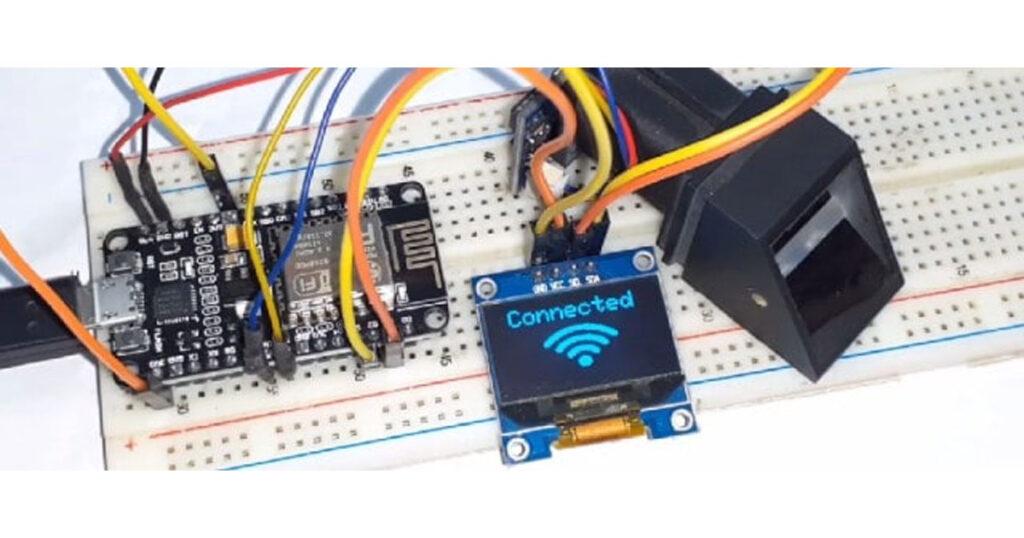
}Result
Once the Code is uploaded the NodeMCU will boot up with the Adafruit logo. And then it will try the connection to the wifi. Once it gets Connected it will display Connected. This log can be viewed on Serial Monitor as well as in OLED Display
So now you can start registering the user using the website. The whole process of registration is explained in the video below. You can follow the video for the registration process. The user fingerprint is taken twice and stored in the EEPROM of the Fingerprint Sensor. It is to be noted that only 127 fingerprints can be stored in this R305/R307 module.

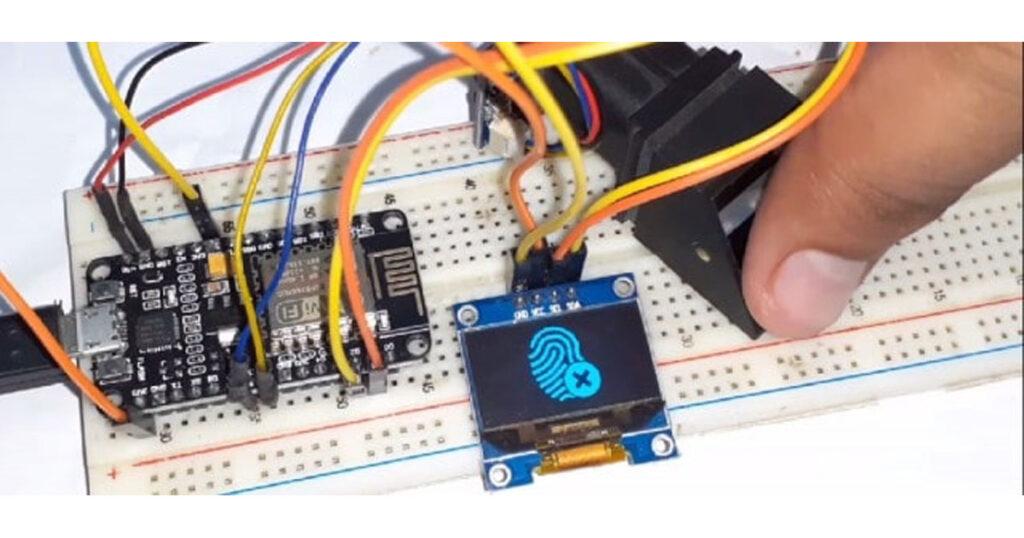
So once the fingerprint of multiple users is stored, you can start scanning and registering the attendance. In case the fingerprint is not matched it will display an error message as shown in the figure below.
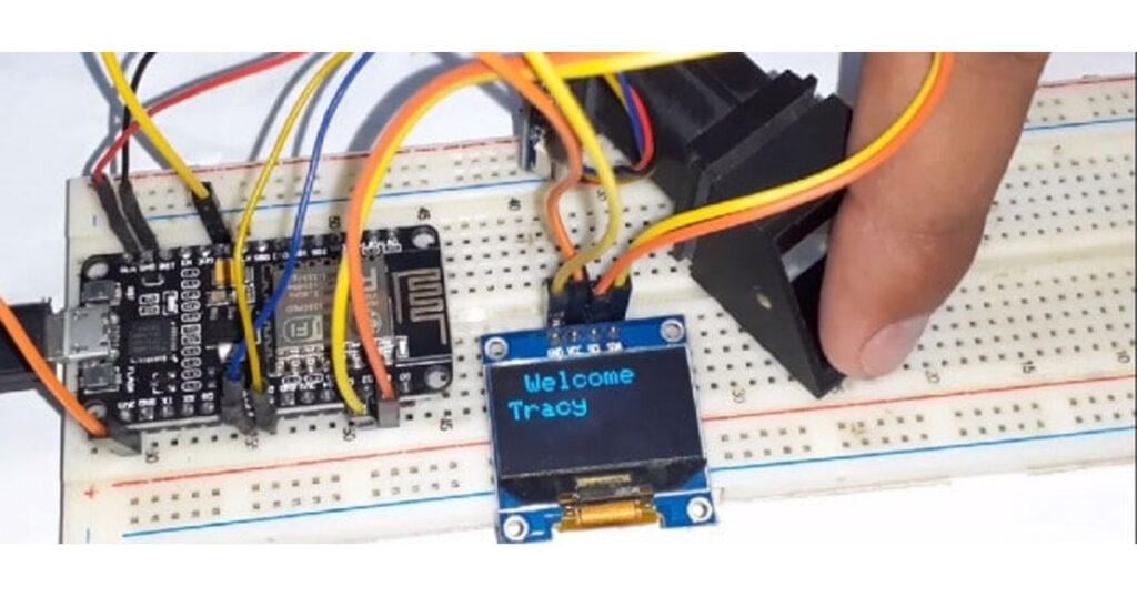
When a registered user scans his finger for the first time it will display the welcome message.
When a registered user scans his finger for the second time it will display the Good-Bye message.

Finally you can see the entire data of the users on the website as shown below:

For understanding the whole process: how to add, update and remove the users from the database follow the video tutorial below.


control reaches end of non-void function [-Werror=return-type]
i am facing thiss error