Tutorial of ESP32 LoRa SX1278 0.96 Inch Blue OLED Display BT Wi-Fi Module for Arduino

The tutorial for the ESP32 LoRa SX1278 0.96 Inch Blue OLED Display BT Wi-Fi Module for Arduino provides a step-by-step guide on setting up and using this module for wireless communication projects. It covers the basics of connecting the module to an Arduino board, configuring the LoRa settings, and displaying data on the built-in OLED screen. Additionally, the tutorial includes code examples for sending and receiving data via LoRa, making it ideal for IoT projects that require long-range communication.

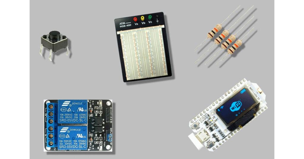
| S.N. | Components Name | Quantity | Purchase Link |
|---|---|---|---|
| 1 | Heltec Wi-Fi LoRa 32 | 1 | RoboticsDnA.in |
| 2 | 12x12x7.3mm Tact Switch – (Pack of 10) | 1 | RoboticsDnA.in |
| 3 | 10k ohm resistor | 1 | RoboticsDnA.in |
| 4 | Relay module | 1 | RoboticsDnA.in |
| 5 | Breadboard | 1 | RoboticsDnA.in |
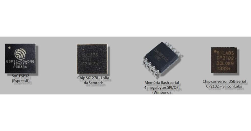
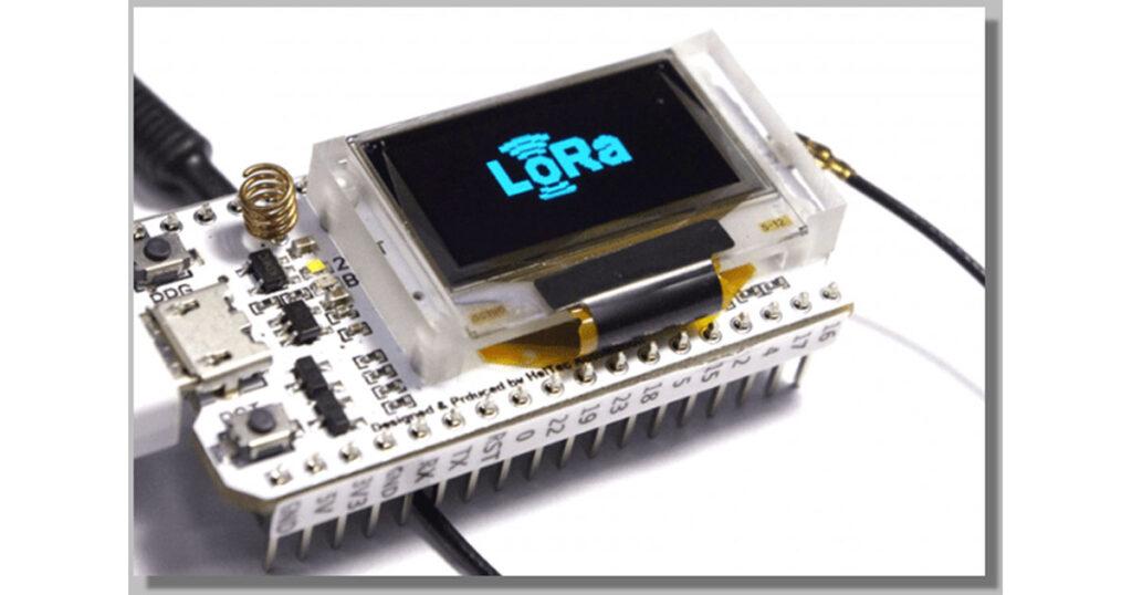
It is a development board that integrates a SoC ESP32-D0WDQ6.
It has a W25Q32FV Serial Flash Memory (SPI / QPI) chip with approximately 32 megabits (4 megabytes) of storage.
A SX1278 LoRa chip is controlled by ESP32.
The USB-Serial interface uses a CP2102 from Silicon Labs.
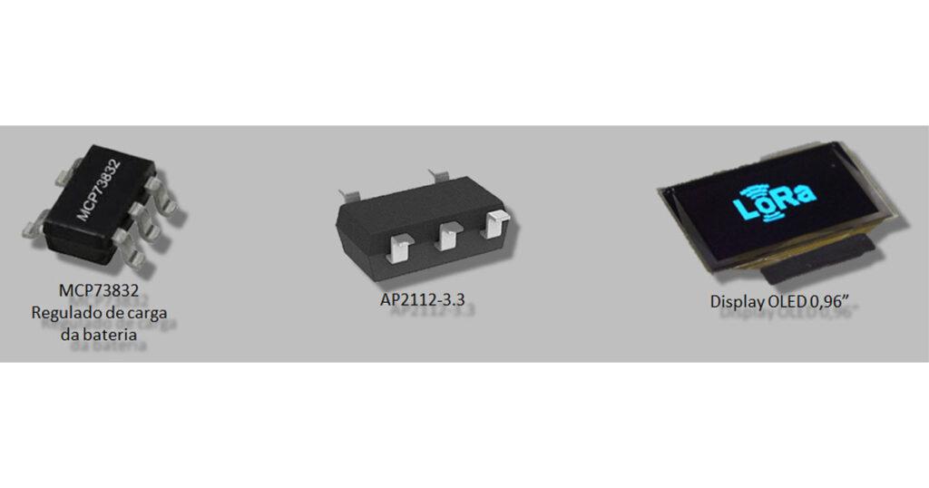
In addition to an MCP73831 / 2, it comes with a Lithium Ion (Li-Ion) or Lithium Polymer (Li-Po) battery charge controller.
And it features a regulator AP2112-3.3 to provide 3.3V and a minimum of 600mA.
The board has two crystals, one from 26MHz to the ESP32, and another from 32MHz to the SX1278.
It has a 0.96″ OLED display, also controlled by the ESP32.
Wiring Diagram of the Heltec WiFi LoRa 32
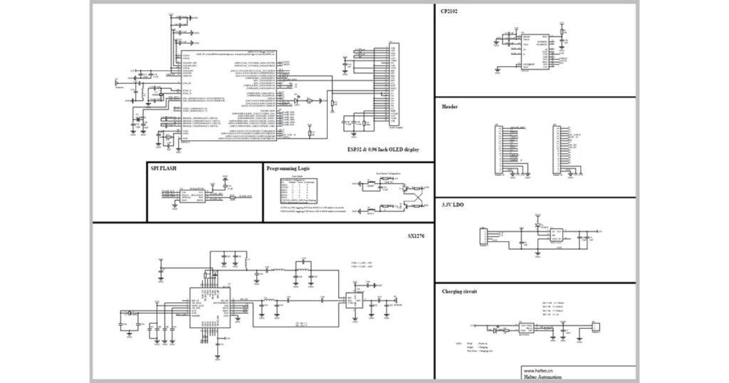
This same wiring diagram serves both the Heltec chip and the TTGO.
Pinout of Heltec WiFi LoRa 32 Card :
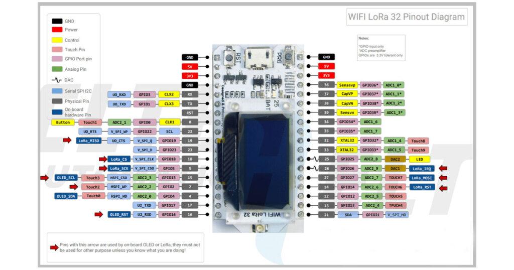
I point out that if you take the traditional ESP32, unlike this image, it will not have the display and the SX1278, which is the Semtech chip.
TTGO X Heltec :

Circuit :
In this circuit, we will detect the push of a button through the GPIO34 (pin 34 of the board), and we will drive the relays of the module through the GPIO22 and 23 (pins 22 and 23), respectively.
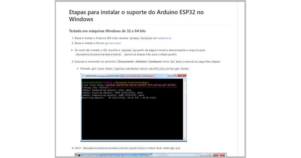
Plate Installation :
To install the board, we can follow the instructions of the Heltec itself in its GIT.
https://github.com/Heltec-Aaron-Lee/WiFi_Kit_series/blob/master/InstallGuide/windows.md
Source Code :
Statements
When you’re referring to the ESP32 pin, what matters is the GPIO. In this step, therefore, we point out that the pin that is connected to the button, as well as the ones that are connected in the relay module. We also have the variable to store the state of the second relay.
//Pino ligado no botão
int btn1 = 34;
//Pinos que são ligados no módulo de relés
int rele1 = 22;
int rele2 = 23;
//variável para guardar o estado do segundo relé
boolean rele2_Ativo = false;
Setup ()
The setup () function must be run once before the loop. We set the pins of the buttons as input, relays as output, and we open the serial port, setting the data rate to 9600 bps.
//A função setup() é executada uma vez antes do loop
void setup()
{
 //Seta os pinos dos botões como entrada
 pinMode(btn1, INPUT);
 //Seta os pinos dos relés como saída
 pinMode(rele1, OUTPUT);
 pinMode(rele2, OUTPUT);
 //Abre a porta serial, definindo a taxa de dados para 9600 bps
 Serial.begin(9600);
}
Loop ()
As for the loop () function, it executes after setup and is repeated continuously. Check if the button was pressed and, if so, we will print this status on the screen. We then turn on relay 1, invert the state of variable relay2_Active, and then we change the state of relay 2. We wait for 1 second and turn off relay 1.
//A função loop() é executada após o setup e é repetida continuamente
void loop()
{
    if (digitalRead(btn1) == HIGH) //Caso o botão 1 foi pressionado
    {
        //Exibe no monitor serial a mensagem entre aspas
        Serial.println("Botão pressionado");
        //Ligamos o relé 1
        digitalWrite(rele1, HIGH);
        //Invertemos o estado da variável rele2_Ativo
        rele2_Ativo = !rele2_Ativo;
        //Mudamos o estado do relé 2
        digitalWrite(rele2, rele2_Ativo );
        //Aguardamos 1 segundo (1000 ms)
        delay(1000);
        //Desligamos o relé 1
        digitalWrite(rele1, LOW);
    }
}
Doing the Upload of Code :
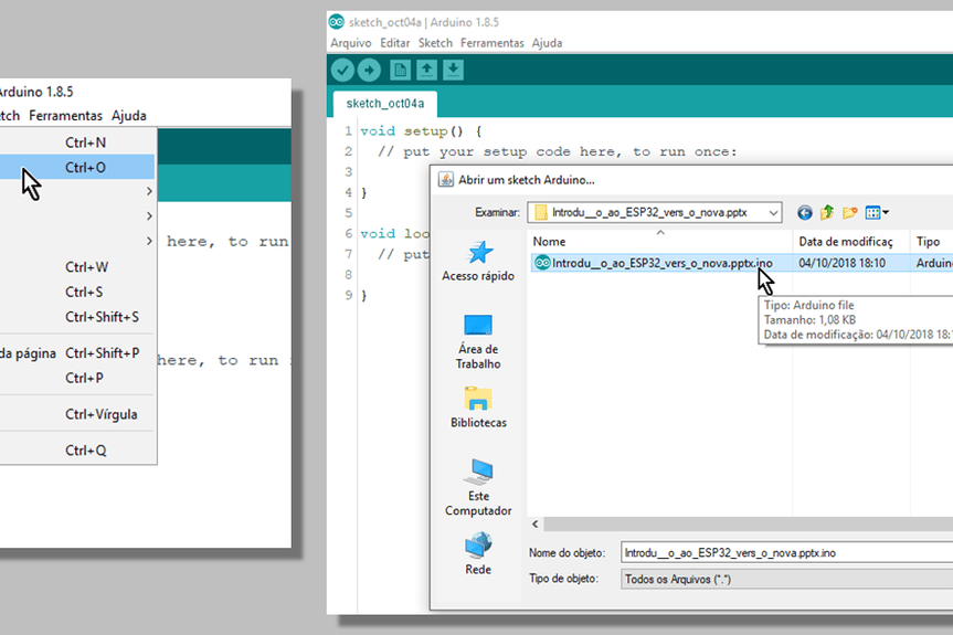
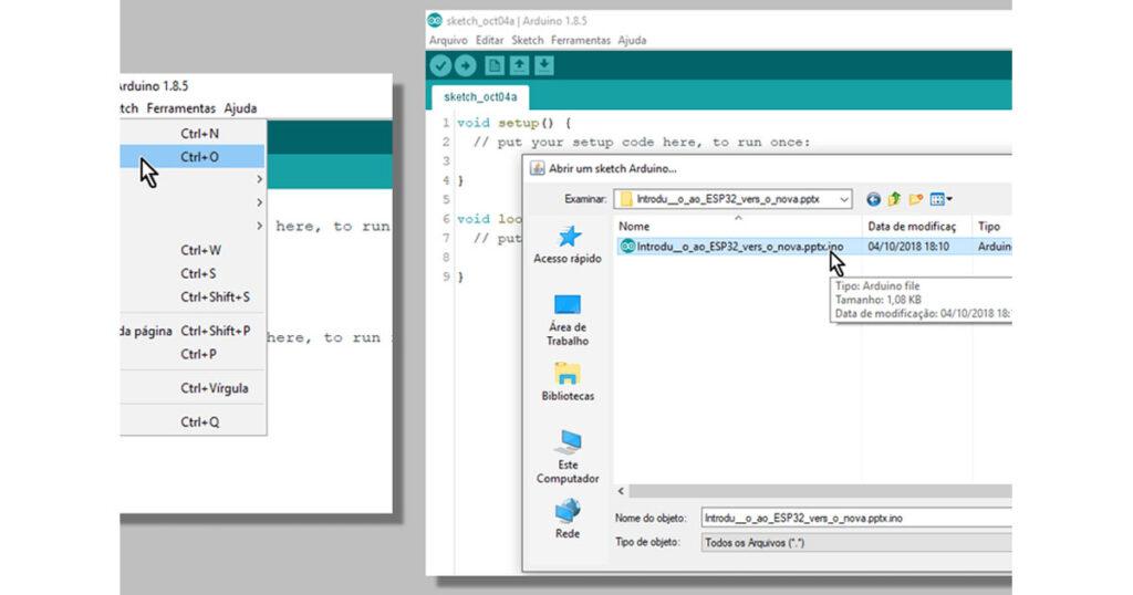
With the IDE open, open the file with the source code by double-clicking the .ino file or through the File menu.
With Heltec connected to USB, select the menu Tools => Card: “Heltec_WIFI_LoRa_32”
Still in the Tools menu, select the COM port on which the Heltec is connected.
Click the UPLOAD button…
… And wait for the conclusion:
Verifying Execution
After recording, we check the execution, click the button to open the Serial Monitor, and then we set the baud rate to 9600.
Press the button, in addition to activating the relays. The following message should appear on the Serial Monitor.