


Specifications:
Hurry and get discounts on all Apple devices up to 20%
Sale_coupon_15
₹244.42 (Inc. GST)
₹207.14 (+18% GST Extra)
In stock
In stock
To pick up today
Free
(Mon-Sat) (Please Place Order Before 1:30 PM)
Rs. 99
Our courier will deliver to the specified address
3-5 Days
Rs. 149
Our courier will deliver to the specified address
4-7 Days
Rs. 69
Payment Methods:
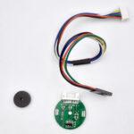
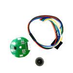
A two-channel Hall effect encoder is used to sense the rotation of a magnetic disk on a rear protrusion of the motor shaft. The encoder board senses the rotation of the magnetic disc and provides a resolution of 48 counts per revolution of the motor shaft when counting both edges of both channels. To compute the counts per revolution of the gearbox output shaft, multiply the gear ratio by 48.
The hall sensors are powered through the VCC and GND pins. VCC can be 3.0 V to 18 V, and the quadrature outputs A and B are digital signals that are either driven low (0 V) by the sensors or pulled to VCC through 10 kΩ pull-up resistors, depending on the applied magnetic field. The A and B outputs are square waves approximately 90° out of phase. The sensors’ comparators have built-in hysteresis, which prevents spurious signals in cases where the motor stops near a transition point. The frequency of the transitions tells you the speed of the motor, and the order of the transitions tells you the direction.
By counting both the rising and falling edges of both the A and B outputs, it is possible to get 48 counts per revolution of the motor shaft. If using just a single edge of one channel (A or B)results in 12 counts per revolution of the motor shaft.

Package Include:
1 x Sensor PCB
1 x connecting cable
1 x Magnet
Only logged in customers who have purchased this product may leave a review.
Out of stock
Out of stock
No account yet?
Create an Account

Reviews
Clear filtersThere are no reviews yet.