

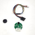
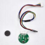
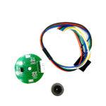
SCX3530 Hall Effect Two Channel Magnetic Encoder
Original price was: ₹225.00.₹214.00Current price is: ₹214.00. (Inc. GST)
₹181.36 (+18% GST Extra)
₹181.36 (+18% GST Extra)
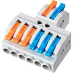
2-to-6 Wiring Block KV-426 Quick Connector
₹49.99 (Inc. GST)
₹42.37 (+18% GST Extra)
₹42.37 (+18% GST Extra)


-
 Pick up from the RoboticsDNA Store in Pune / Dunzo
-
Same Day Delivery in Pune
-
 via Delhivery.com (Express Mode)
-
via Delhivery.com (Surface Mode)
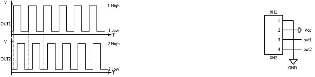
A One-channel Hall effect encoder is used to sense the rotation of a magnetic disk on a rear protrusion of the motor shaft. The encoder board senses the rotation of the magnetic disc and provides a resolution of 48 counts per revolution of the motor shaft when counting both edges of both channels. To compute the counts per revolution of the gearbox output shaft, multiply the gear ratio by 48.
The hall sensors are powered through the VCC and GND pins. VCC can be 3.0 V to 18 V, and the quadrature outputs A and B are digital signals that are either driven low (0 V) by the sensors or pulled to VCC through 10 kΩ pull-up resistors, depending on the applied magnetic field. The A and B outputs are square waves approximately 90° out of phase. The sensors’ comparators have built-in hysteresis, which prevents spurious signals in cases where the motor stops near a transition point. The frequency of the transitions tells you the speed of the motor, and the order of the transitions tells you the direction.
By counting both the rising and falling edges of both the A and B outputs, it is possible to get 48 counts per revolution of the motor shaft. If using just a single edge of one channel (A or B)results in 12 counts per revolution of the motor shaft.
- RED – DC Motor Supply Voltage
- BLACK – DC Motor GND
- GREEN – Encoder GND
- BLUE – Encoder +5V
- YELLOW – Encoder B Signal
- WHITE – Encoder A Signal
*Note: Pinout/color will be change as per circuit.
You may also like :
Package Include:
1 x Sensor PCB
1 x connecting cable
1 x Magnet
 Overview
 Processor
 Display
 RAM
RAM
 Storage
 Video Card
 Connectivity
 Features
 Battery
 General
Related Products

Spindle Motor with ER11 Chuck – Compatible for 3018 2418 1610 3020 CNC Machines
In stock
Original price was: ₹1,500.01.₹1,366.99Current price is: ₹1,366.99. (Inc. GST)
₹1,158.47 (+18% GST Extra)
₹1,158.47 (+18% GST Extra)
SKU:
RDNA-Z113.2

SN-01B WIRE CRIMPING TOOL (20-28AWG – 0.08-0.5 MM) for Non-Insulated Terminal
In stock
Original price was: ₹1,059.00.₹1,006.00Current price is: ₹1,006.00. (Inc. GST)
₹852.54 (+18% GST Extra)
₹852.54 (+18% GST Extra)
SKU:
RDNA-Z101

3.2V 3.7V Light Control +Radar Body Induction Solar Lamp Circuit Board Solar LED Driver Board With Remote Control
In stock
₹250.00 (Inc. GST)
₹211.86 (+18% GST Extra)
₹211.86 (+18% GST Extra)
SKU:
RDNA-A346| RDNA-D339

Dual USB 5V 2.4A Micro/Type-C LED USB Mobile Power Bank 18650 Charging Module Lithium Battery Charger Board Circuit Protection
In stock
₹241.90 (Inc. GST)
₹205.00 (+18% GST Extra)
₹205.00 (+18% GST Extra)
SKU:
RDNA-C808.1

16mm 12-24V 3Pins Toggle Switch
In stock
₹185.00 (Inc. GST)
₹156.78 (+18% GST Extra)
₹156.78 (+18% GST Extra)
SKU:
RDNA-B685.1

20mm x 5mm Neodymium Disc Strong Magnet
In stock
₹70.80 (Inc. GST)
₹60.00 (+18% GST Extra)
₹60.00 (+18% GST Extra)
SKU:
RDNA-E290.1
Reviews
Clear filtersThere are no reviews yet.