


Specifications:
Hurry and get discounts on all Apple devices up to 20%
Sale_coupon_15
₹649.00 (Inc. GST)
₹550.00 (+18% GST Extra)
Out of stock
Out of stock
To pick up today
Free
(Mon-Sat) (Please Place Order Before 1:30 PM)
Rs. 99
Our courier will deliver to the specified address
3-5 Days
Rs. 149
Our courier will deliver to the specified address
4-7 Days
Rs. 69
Payment Methods:

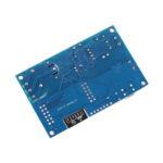
| Number | Name | Function | Number | Name | Function |
| 1 | GND | Power ground | 13 | IO10 | GPIO10 |
| 2 | Relay | The relay drive port is driven by IO5 by default. If you want to use other I / O to drive the relay, you can remove R14, and then connect the I / 0 of the drive relay to this Relay pin | 14 | MISO | Slave output input |
| 3 | IO2 | GPIO2; UART1_TXD | 15 | IO13 | GPIO13; HSPI_MOSI; UART0_CTS |
| 4 | IO4 | GPIO4 | 16 | IO14 | GPI014; HSPI_CLK |
| 5 | RX | UART0_RXD; GPIO3 | 17 | ADC | A / D conversion result. Input voltage 0 ~ 1V, value : 0 ~ 1024 |
| 6 | 3V3 | 3.3V power supply | 18 | 3V3 | 3.3V power supply |
| 7 | SCLK | clock | 19 | MOSI | output Slave input |
| 8 | IO15 | GPIO15; MTD0; HSPICS; UART0_RTS | 20 | IO9 | GPIO9 |
| 9 | IO0 | GPIO0 | 21 | CS0 | Chip Select |
| 10 | IO5 | GPIO5 | 22 | IO12 | GPIO12; HSPI_MIS0 |
| 11 | TX | UARTO_TXD; GPIO1 | 23 | IO16 | GPIO 16 |
| 12 | 5V | 5V power supply | 24 | GND | Power ground |
Packing List:
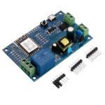
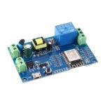
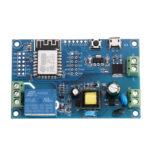
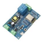
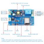
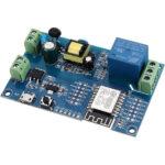
1 x AC90-250V ESP8266 Wireless WIFI Relay Module 1 Channel ESP-12F Wifi Development Board AC/DC 5V/7-28V/5-80V Power Supply
Only logged in customers who have purchased this product may leave a review.
Out of stock
Out of stock
No account yet?
Create an Account

Reviews
Clear filtersThere are no reviews yet.