
How to Interface the 1.8-Inch TFT LCD Module (128 x 160) with an Arduino Using 4 IO SPI Interface

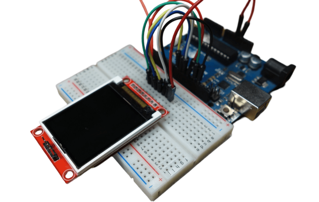
The 1.8-Inch TFT LCD Module with a 128 x 160 resolution and 4 IO SPI interface is a popular choice for adding a vibrant display to your Arduino projects. Whether you’re working on a simple data logger or a more complex graphical user interface, this tutorial will guide you through the steps to get your TFT display up and running with an Arduino.
What You’ll Need
- 1.8-Inch TFT LCD Module (128 x 160 resolution)
- Arduino Board (e.g., Arduino Uno, Nano, Mega)
- Breadboard and Jumper Wires
Initializing the display
The TFT display communicates with the Arduino via SPI communication, so you need to include the SPI library on your code. We also use the TFT library to write and draw on the display.
#include <TFT.h>
#include <SPI.h>
Then, you need to define the CS, A0 (or DC) and RST pins:
#define cs 10
#define dc 9
#define rst 8
Create an instance of the library called TFTscreen:
TFT TFTscreen = TFT(cs, dc, rst);
Finally, in the setup(), you need to initialize the library:
TFTscreen.begin();
Display text
To write text on the display, you can customize the screen background color, font size and color.
To set the background color, use:
TFTscreen.background(r, g, b);
In which, r, g and b are the RGB values for a given color. To choose font color:
TFTscreen.stroke(r, g, b);
To set the font size:
TFTscreen.setTextSize(2);
You can increase or decrease the number given as argument, to increase or decrease font size.
Finally, to draw text on the display you use the following line:
TFTscreen.text("Hello, World!", x, y);
In which “Hello, World!” is the text you want to display and the (x, y) coordinate is the location where you want to start display text on the screen.
Step 1: Understanding the Pinout
The 1.8-inch TFT LCD typically has the following pins:
- VCC: Power supply (3.3V or 5V)
- GND: Ground
- CS: Chip Select pin
- RST: Reset pin
- DC (or RS): Data/Command pin
- MOSI: Master Out Slave In (SPI data line)
- SCK (or CLK): Serial Clock line
- LED: Backlight control (optional, often tied to VCC or controlled via PWM)
Step 2: Connecting the TFT Display to the Arduino
Here’s how to wire the TFT display to your Arduino board:
| TFT Pin | Arduino Pin |
|---|---|
| VCC | 3.3V or 5V |
| GND | GND |
| CS | Pin 10 |
| RST | Pin 9 |
| DC/RS | Pin 8 |
| MOSI | Pin 11 |
| SCK/CLK | Pin 13 |
| LED | 3.3V (via a resistor) or PWM Pin for brightness control |
Note: The above connections are based on the default SPI pins for the Arduino Uno. If you’re using a different Arduino board, you might need to adjust the MOSI, SCK, and other connections accordingly.
Step 3: Installing the Necessary Libraries
To interface with the TFT LCD, you’ll need the Adafruit GFX Library and the Adafruit ST7735 Library (or a similar library depending on your module).
- Open the Arduino IDE.
- Go to Sketch > Include Library > Manage Libraries.
- Search for Adafruit GFX Library and click Install.
- Search for Adafruit ST7735 and ST7789 Library and click Install.
Step 4: Writing the Code
Now that everything is connected, it’s time to write the code to initialize the display and test it by showing some basic text.
/*
 * Rui Santos
 * Complete Project Details https://randomnerdtutorials.com
 */

// include TFT and SPI libraries
#include <TFT.h>
#include <SPI.h>

// pin definition for Arduino UNO
#define cs   10
#define dc   9
#define rst  8


// create an instance of the library
TFT TFTscreen = TFT(cs, dc, rst);

void setup() {

  //initialize the library
  TFTscreen.begin();

  // clear the screen with a black background
  TFTscreen.background(0, 0, 0);
  //set the text size
  TFTscreen.setTextSize(2);
}

void loop() {

  //generate a random color
  int redRandom = random(0, 255);
  int greenRandom = random (0, 255);
  int blueRandom = random (0, 255);

  // set a random font color
  TFTscreen.stroke(redRandom, greenRandom, blueRandom);

  // print Hello, World! in the middle of the screen
  TFTscreen.text("Hello, World!", 6, 57);

  // wait 200 miliseconds until change to next color
  delay(200);
}
Step 5: Upload the Code
- Connect your Arduino to your computer using a USB cable.
- Select the correct board and port from the Tools menu in the Arduino IDE.
- Click Upload to upload the sketch to your Arduino.
Step 6: Power Up and Test
Once the code is uploaded, your TFT display should power up and show the “Hello, World!” text along with a red line and a green rectangle. If everything is working correctly, you can start experimenting with more complex graphics and text.
Common Issues and Troubleshooting
- No Display Output: Double-check your wiring, especially the power connections (VCC and GND). Ensure that the SPI connections (MOSI, SCK, CS) are correct.
- Flickering or Unstable Display: This could be due to insufficient power. Make sure the VCC pin is connected to a stable 3.3V or 5V source.
- Incorrect Colors or Distorted Graphics: This might be due to incorrect initialization in the code. Ensure that you’re using the correct initialization command for your specific TFT module.
Display images :
The 1.8 TFT display can load images from the SD card. To read from the SD card you use the SD library, already included in the Arduino IDE software. Follow the next steps to display an image on the display:
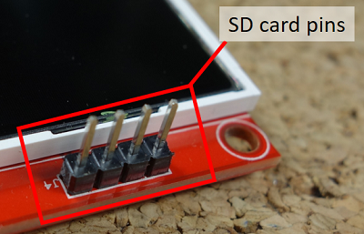
1) Solder header pins for the SD card. There are four pins opposite to the display pins, as shown in figure below.
2) The display can load images bigger or smaller than the display size (160 x 128 px), but for better results, edit your image size to 160 x 128 px.
3) The image should be in .bmp format. To do that, you can use a photo editing software and save the image as .bmp format.
4) Copy the image to the SD card and insert it on the SD card slot at the back of the display.
5) Wire the SD card pins to the Arduino by following the table below:
| SD card on TFT display | Wiring to Arduino Uno |
| CS | 4 |
| MOSI | 11 |
| MISO | 12 |
| SCK | 13 |
Both the display and the SD card work with SPI communication, so you’ll have pins on the Arduino with two connections.
6) In the Arduino IDE go to File > Examples > TFT > Arduino > TFTBitmaLogo.
7) Edit the code, so that it searches for your image. Replace the “arduino.bmp” with the name of your image:
// now that the SD card can be access, try to load the image file
logo = TFTscreen.loadImage("arduino.bmp");
8) Upload the code to your Arduino.
Note: some people find issues with this display when trying to read from the SD card. We don’t know why that happens. In fact, we tested a couple of times and it worked well, and then, when we were about to record to show you the final result, the display didn’t recognized the SD card anymore – we’re not sure if it’s a problem with the SD card holder that doesn’t establish a proper connection with the SD card. However, we are sure these instructions work, because we’ve tested them.
Conclusion
Interfacing the 1.8-Inch TFT LCD Module with an Arduino is a straightforward process that opens up a world of possibilities for your projects. Whether you’re displaying sensor data, creating a simple user interface, or just experimenting with graphics, this small yet powerful display is a great addition to any electronics project.
With the basics covered in this guide, you can now dive deeper into customizing your display, adding more complex graphics, or integrating other components to create truly interactive projects. Happy tinkering!