
Door lock With Biometric Face for Security Using ESP32-CAM-MB MICRO USB Module for ESP32 CAM Development Board
Hello everyone, in this instructable we will create a key tool that uses a face scanner. Surely there are friends who feel afraid about the security of your room or house or are bored with conventional door lock models that are just like that. Therefore, we created a facial scanning based key model which is of course easy to design and has a very affordable price.
The goal itself is to create a door lock device that has a face detection feature so that the security of the room/house can be maintained and makes it easier for users so that they no longer have to carry the door key everywhere.
So come on, follow us until the end!!!
| S.N. | Components Name | Quantity | Purchase Link |
|---|---|---|---|
| 1 | Ai Thinker ESP32 CAM Development Board Wi-Fi+ Bluetooth Camera Module | 1 | RoboticsDnA.in |
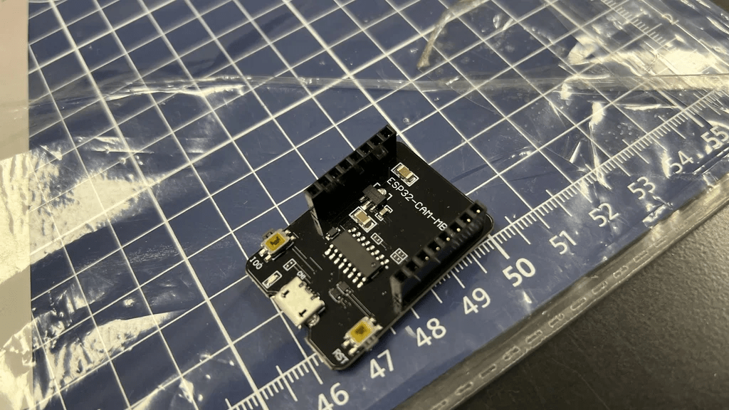
| 2 | Ai ThinkeESP32-CAM-MB MICRO USB Module for ESP32 CAM Development Board | 1 | RoboticsDnA.in |
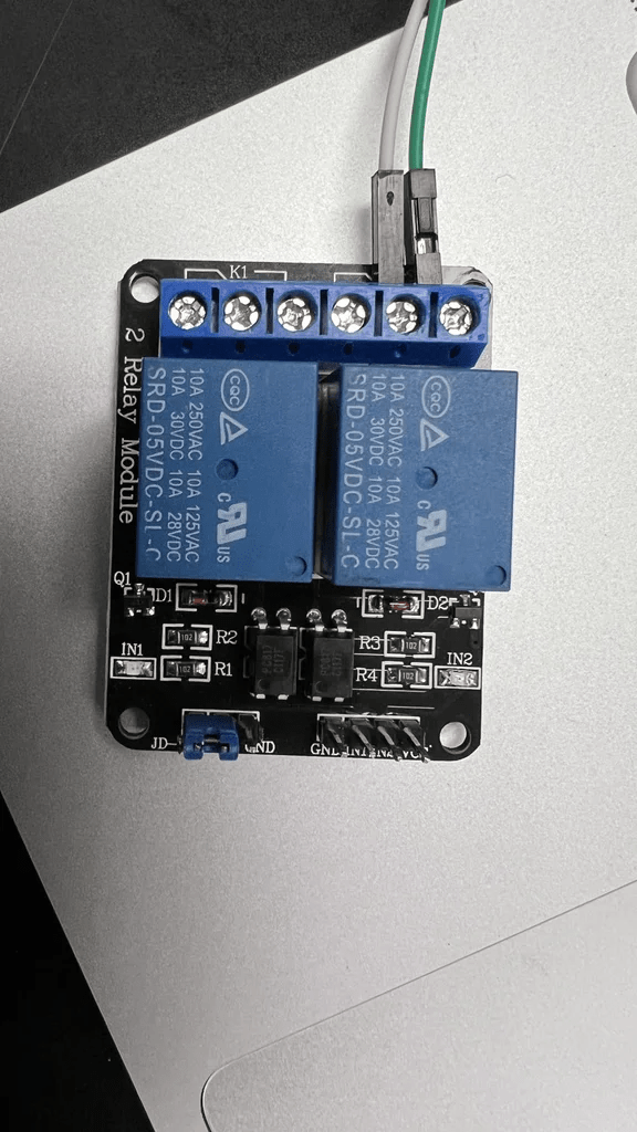
| 3 | BESTEP 2 Channels 5V Relay Module High and Low Triggering | 1 | RoboticsDnA.in |
| 4 | USB to Type-C Cable 2.4A 1 Meter Fast Charging High Speed Data Transfer | 1 | RoboticsDnA.in |
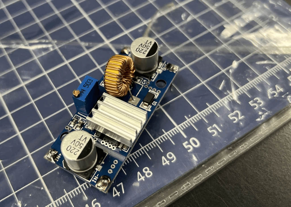
| 5 | 24V/12V to 5V 5A Power Module DC-DC XY-3606 | 1 | RoboticsDnA.in |
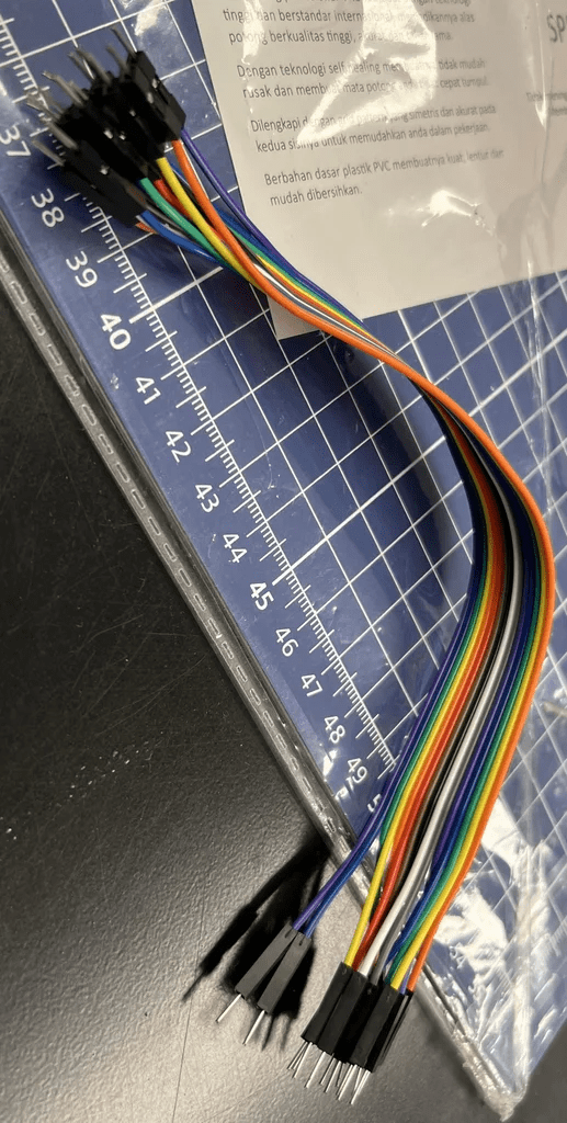
| 6 | Connecting Wires | 10 | RoboticsDnA.in |
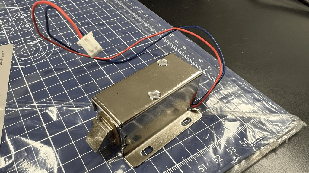
| 7 | 12V 1Amp Solenoid Actuator Door Lock | 1 | RoboticsDnA.in |
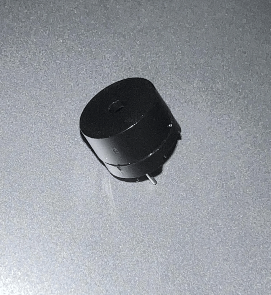
| 8 | 5V Active Buzzer- 5 Pcs. | 1 | RoboticsDnA.in |
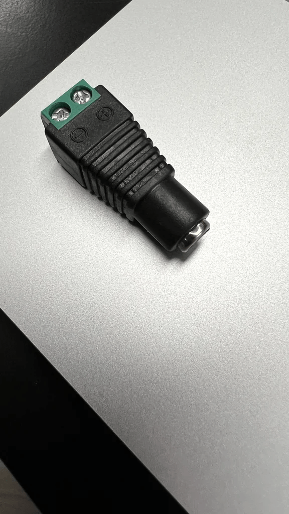
| 9 | Female DC Power Jack Adapter Connector Plug | 1 | RoboticsDnA.in |
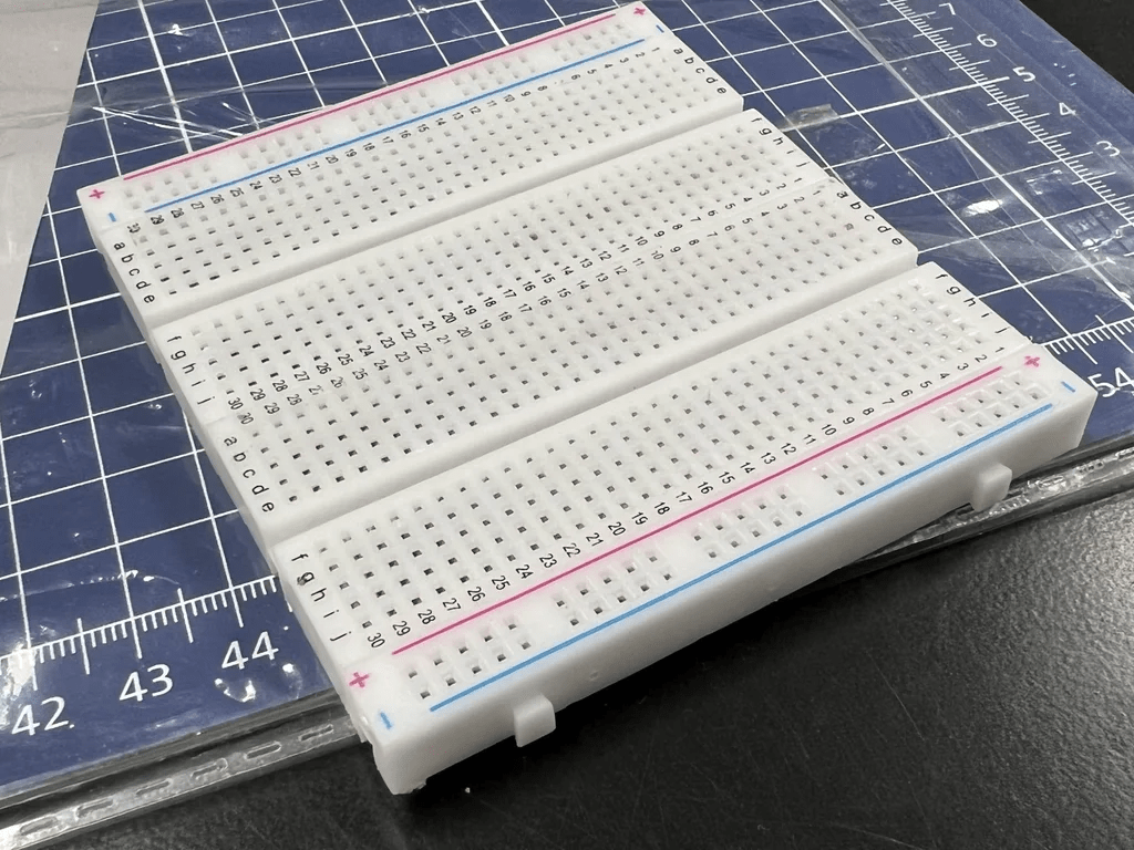
| 10 | GL12 Breadboard 840 Points | 1 | RoboticsDnA.in |
| 11 | 22k Ohm 0.25W Metal Film Resistor | 1 | RoboticsDnA.in |
| 12 | 100pcs 5mm Light Assorted Kit DIY LEDs Set | 1 | RoboticsDnA.in |
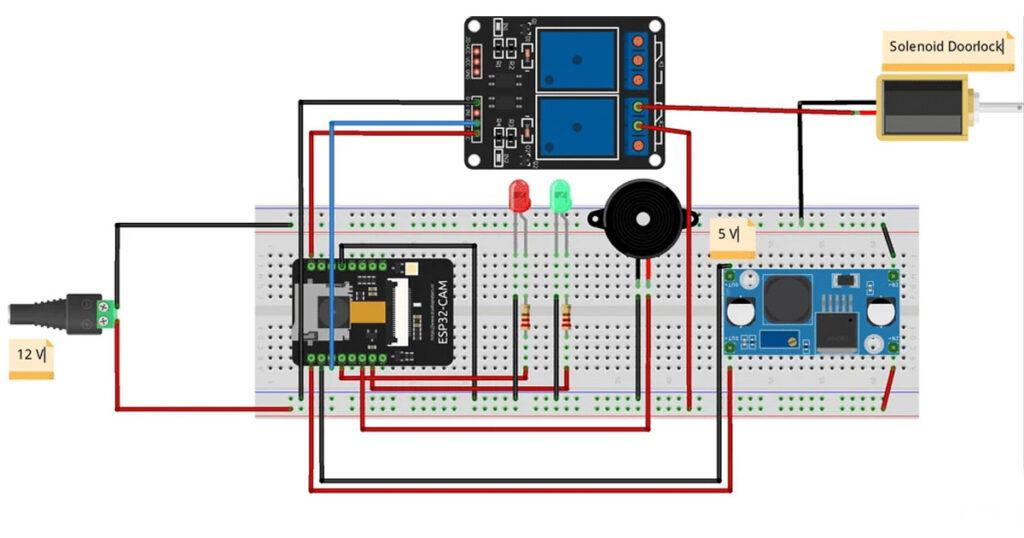
This is a schematic of the tool that will be made later, with the DC jack connector connected to a 12V power supply.
Block Diagram
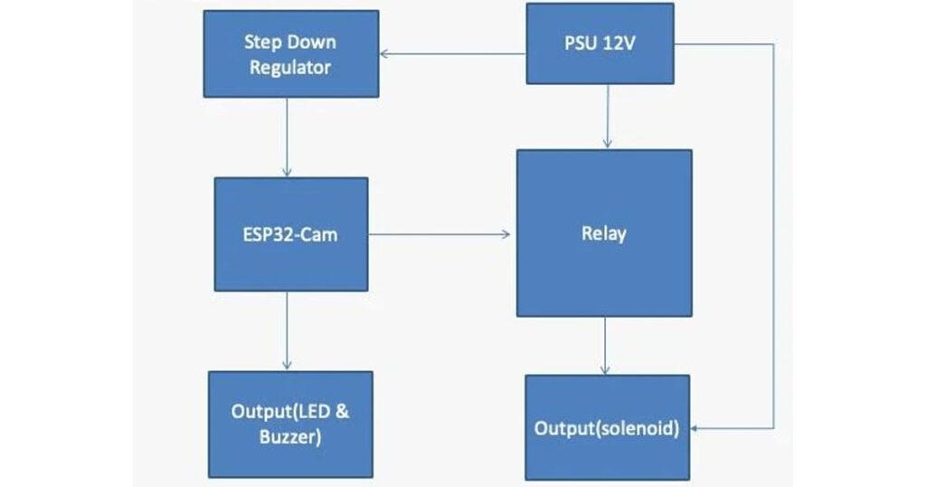
The following is a block diagram of the tool that will be made
Flow Chart

This is a flowchart of the tool from start to finish
Coding
This is the coding used to run the tool. Before running the code, there are several libraries that need to be installed first, such as the Firebase Arduino client library for ESP8266 and ESP32, esp32cam, NTP client, and Arduino web sockets.
Component
So those are the tools and materials needed to make this key model. If friends want a model that is more unified and more durable then you can use a PCB (double layer through hole PCB measuring 12x18cm) as well as a 40 pin female header and solder it. However, if you want a simple tool, you are welcome to use a breadboard.
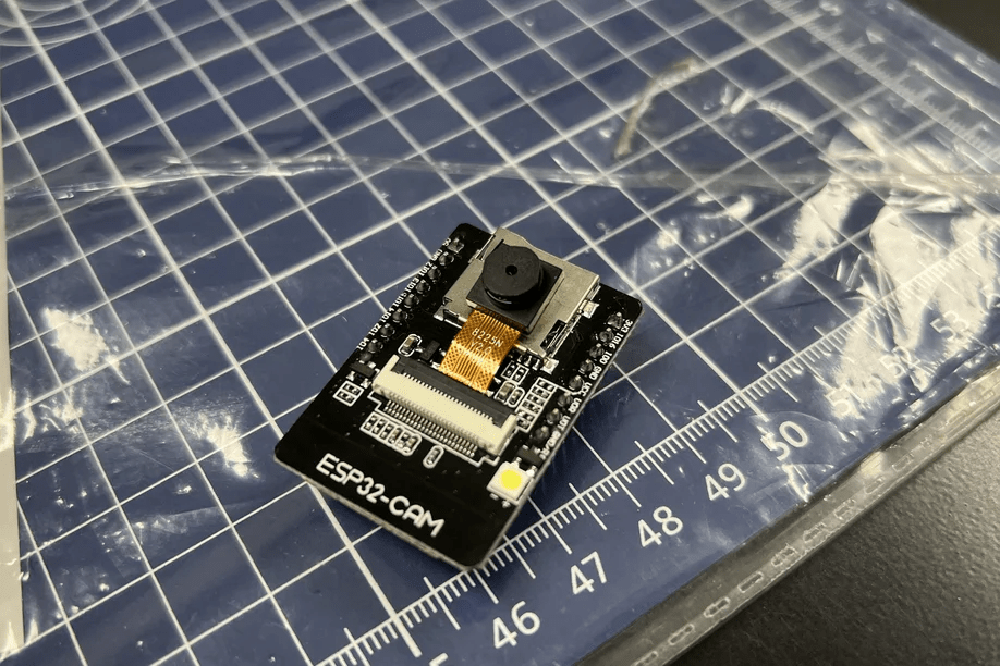
ESP32-CAM
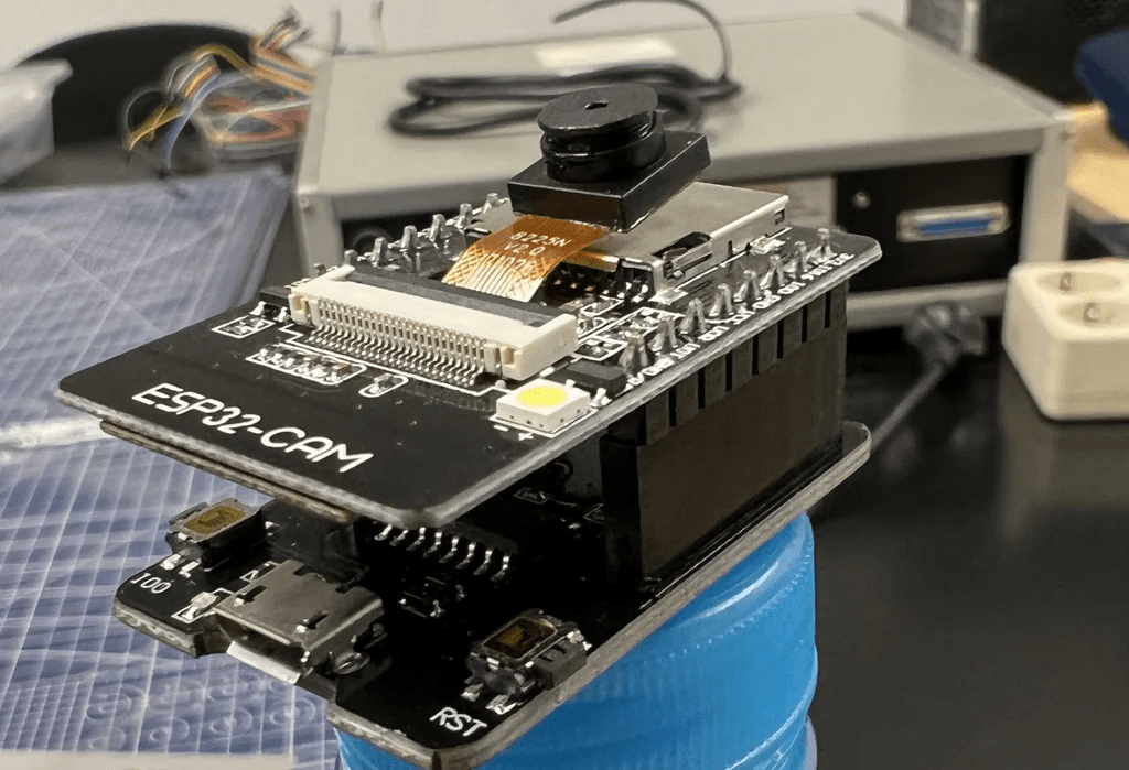
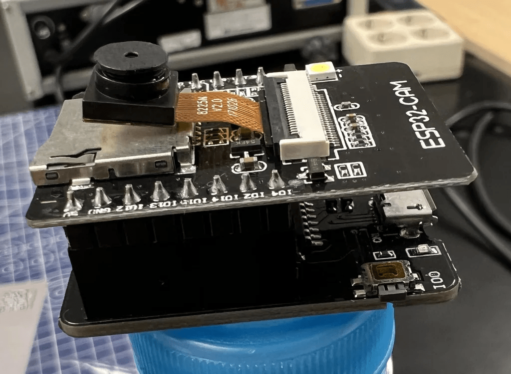
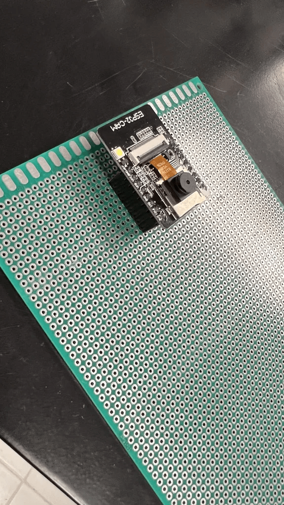
Install the ESP32-CAM above the ESP32-CAM MB so that later the program can be uploaded to the ESP32-CAM board which is useful as the center of this tool. If you have uploaded it via the esp32-cam MB then we can remove the esp cam board from the mb and the program will still be stored on the board and can be attached to the PCB or breadboard.
Power Supply
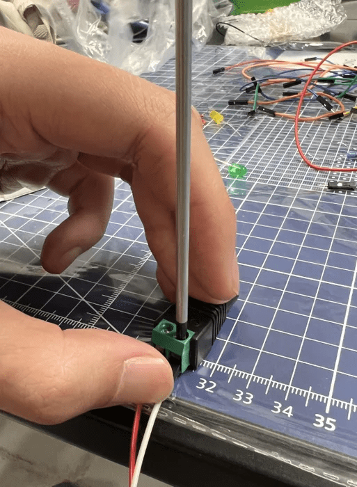
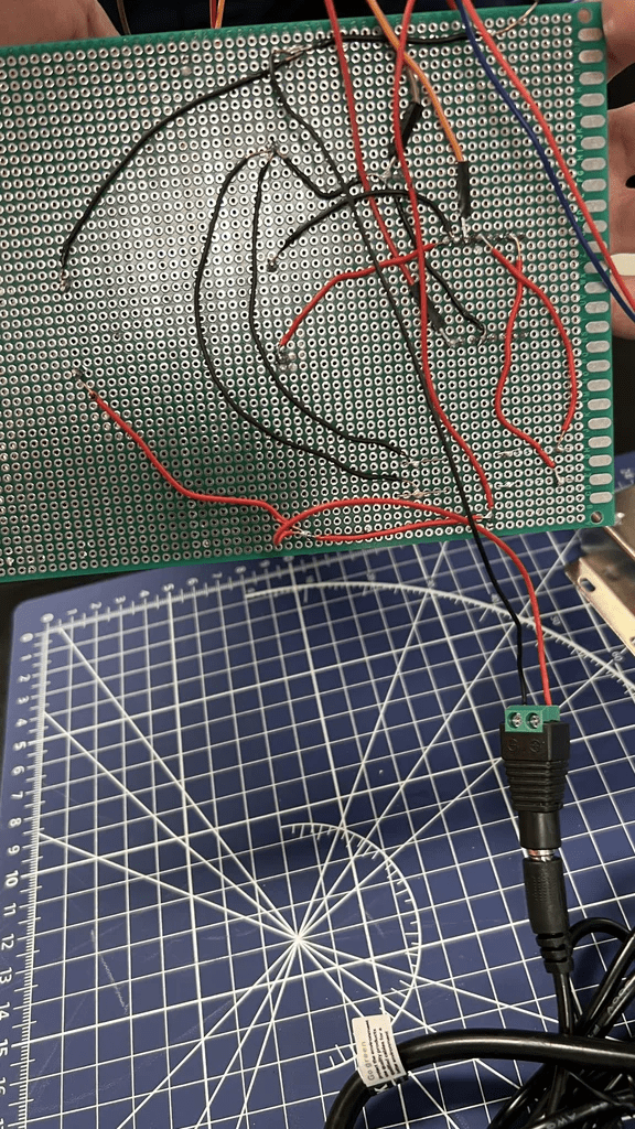
This step requires a screwdriver + for the DC connector, you can rotate the nail part to loosen the contents, then insert the jumper cable into it, then rotate it again to tighten it.
Power Supply to Breadboard
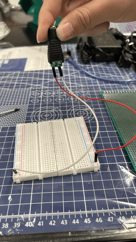
The jumper cable from the DC Connector is connected to the breadboard following the positive and negative axes. *Make sure not to make a mistake to prevent a short circuit*
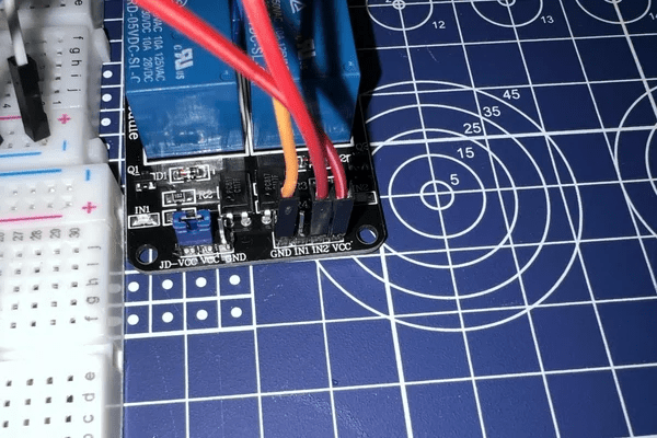
Relay
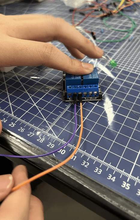
Use a screwdriver + again to loosen the common and normally closed part of the relay (free to use the first or second relay, here we use the second relay), then connect the jumper cable.
Solenoid, Relay, Dan DC Connector
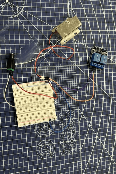
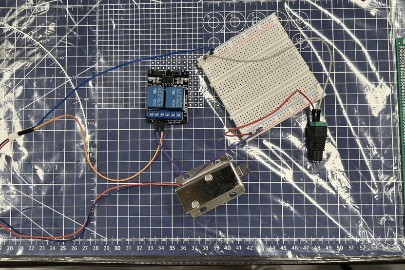
Connect the positive axis solenoid to the normally closed relay and the negative axis to the breadboard. then connect the common relay to the + breadboard.
DC Step Down Regulator
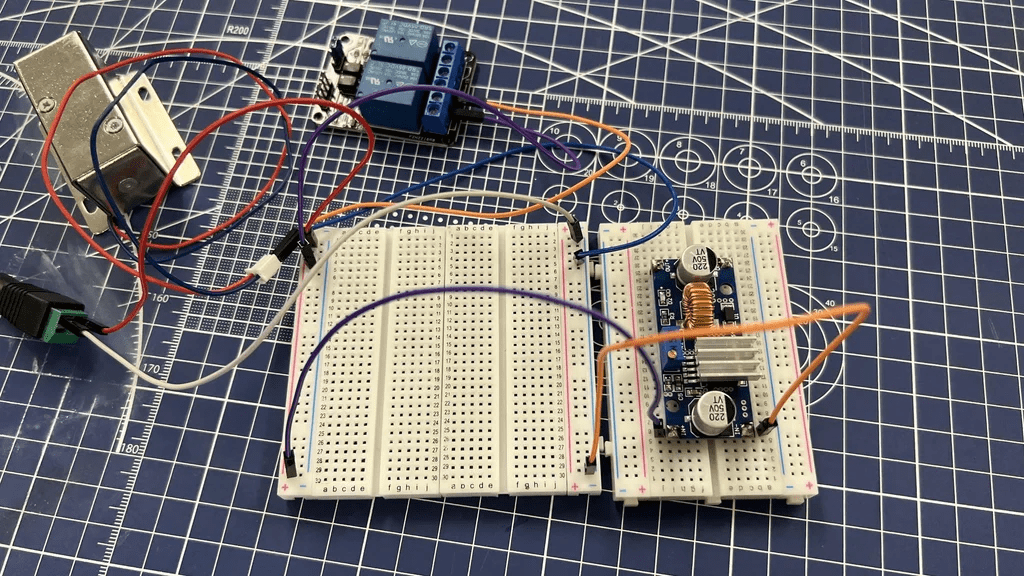
Next connect IN+ regulator to + breadboard then IN- to – breadboard. For the DC female jack connector, connect the + connector to the + breadboard adjacent to the common relay, and the – connector to the – breadboard as shown in the picture above.
Upload Programs From Computer
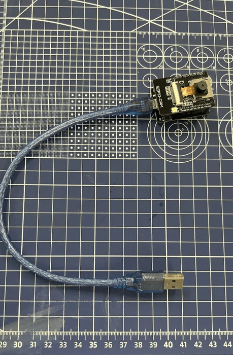
Prepare a micro USB to USB type-A cable to connect to the ESP32-Cam MB, then connect the cable to the computer and upload the program from the computer to the ESP32-cam board.
ESP32-CAM Dan DC Step Down Regulator
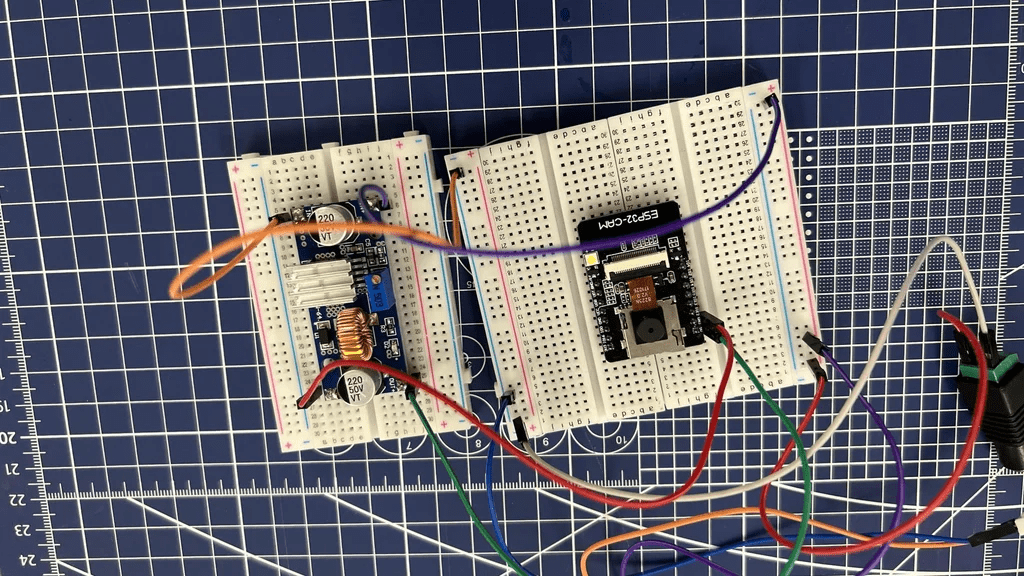
Connect OUT- regulator to ground(gnd) esp32 then OUT+ to 5V esp32.
Relay Ke ESP32-CAM
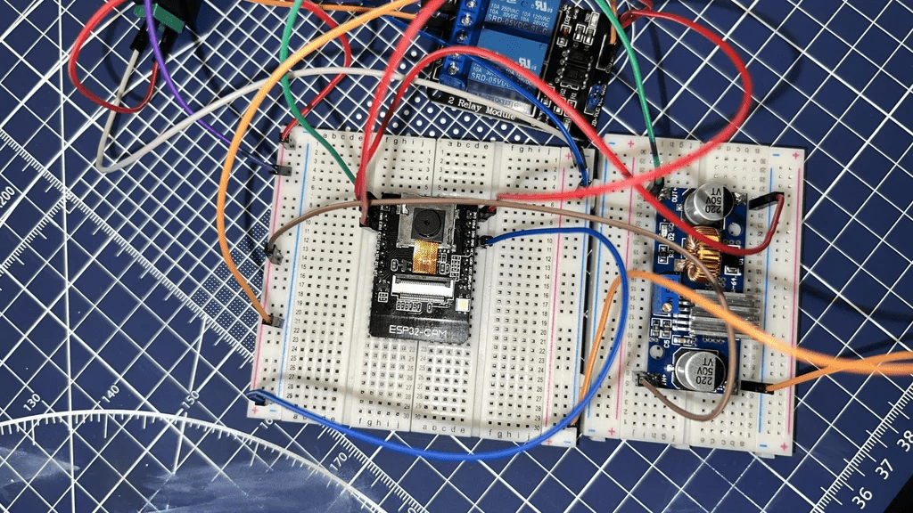
Connect the ground relay to – breadboard, then In2 relay to gpio12 from esp32-cam and vcc to 3v3 esp32-cam, keep in mind because we will use LEDs so we will need ground from esp32-cam for led so connect ground esp32-cam to – breadboard.
Added LED’s
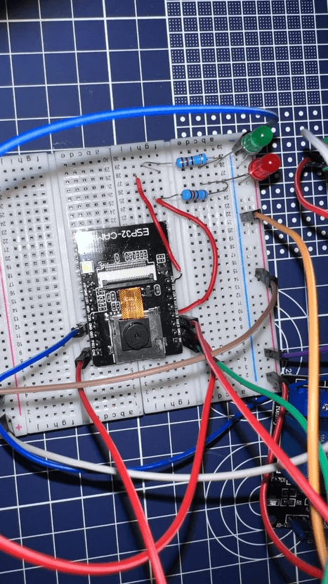
To add an LED, we need a resistor so that the LED doesn’t get hot and explode, first connect the negative pole of the LED to the – breadboard then connect the resistor to the + of the LED. Because in our program we use io13 for the red led and io4 for the green led, we connect the 2 leds using a cable according to the io that has been specified in the program. Friends, you can see the image above for clearer details.
If Using a PCB Board
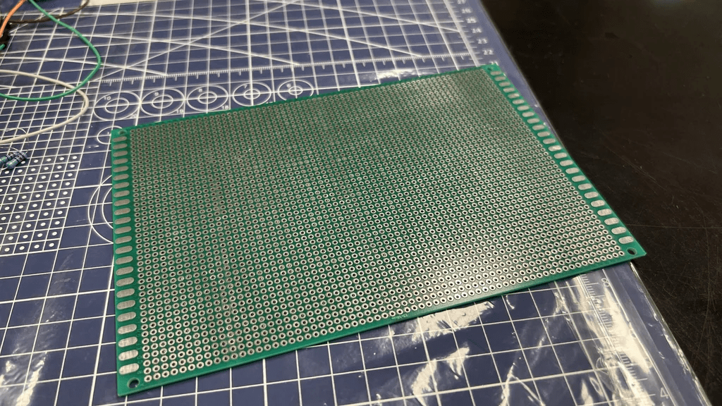
If we want to use a PCB then we will need a double layer through hole PCB measuring 12x18cm and a 40 pin female header. First, make sure the 40 pin female header is cut according to the ESP32-Cam gpio so that later when soldering we can remove and install the ESP32-Cam board from the PCB board.
Wiring & Solder
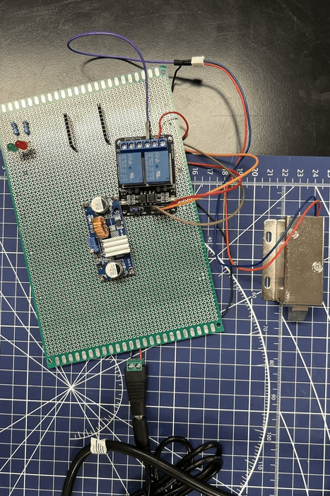
Solder the cables according to the circuit using the breadboard, then you can adjust the placement of the components on the PCB board. Friends, you can see the results of our soldering and wiring in the picture above.
Casing
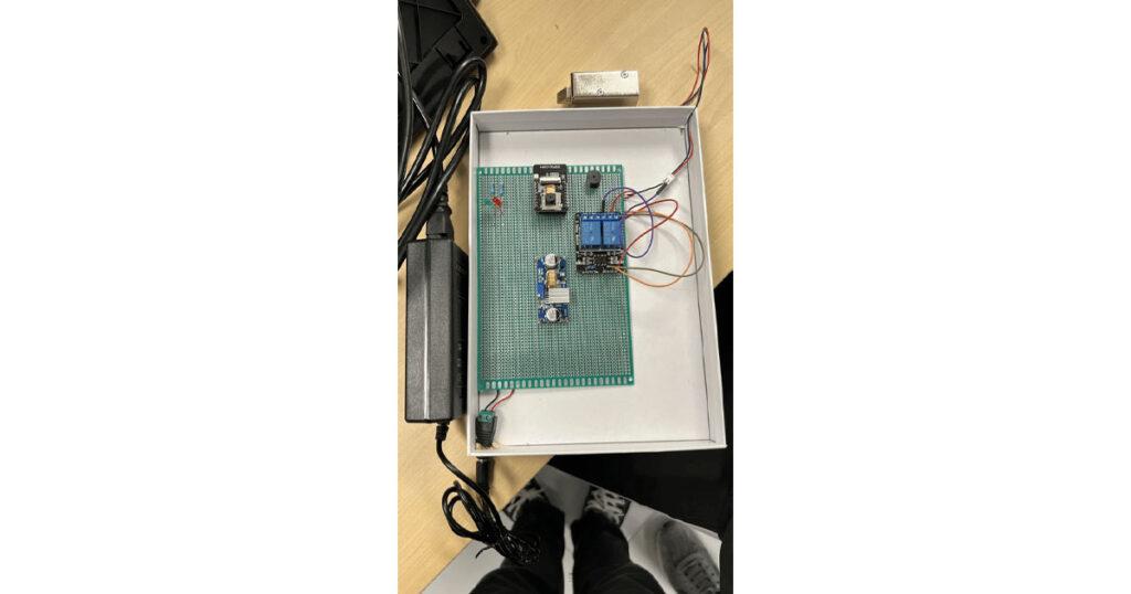
Once it’s neat, we can add a casing to protect the components and give it a bit of an attractive appearance. Here we use a white box then close it and make holes in the power supply and input output devices (camera, LED). If so, we just need to connect the power source to our tool and we can try using the tool
If it's still not clear, friends, you can watch the video that we made above, in this video we also do a demo of our tool.