
Ai Thinker LoRa-Ra-01 RF Transceiver LoRa Module
Introduction :
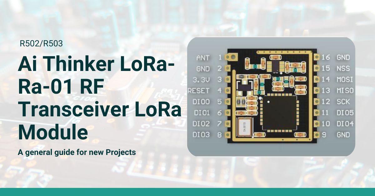
Ra-01 LoRa Module Overview
The Ra-01 LoRa Module is designed for ultra-long-distance spread spectrum communication, supporting LoRa™ and FSK remote modulation and demodulation. It is widely used in networking scenarios such as automatic meter reading, building automation, security systems, and remote irrigation systems, making it ideal for IoT (Internet of Things) applications.
Key Features:
- LoRa™ Spread Spectrum Technology: Provides ultra-long-distance communication with strong anti-interference capabilities.
- High Sensitivity: Receive sensitivity as low as -141 dBm, making it highly efficient in low signal environments.
- Multiple Modulation Support: LoRa, FSK, GFSK, MSK, GMSK, and OOK modulation modes are supported.
- Programmable Bit Rate: Up to 300 Kbps.
- Automatic RF Detection: Supports automatic RF signal detection, CAD mode, and high-speed AFC (Automatic Frequency Control).
- Packet Support: Supports CRC-enabled packets of up to 256 bytes.
- Half-Duplex Communication: Supports SPI half-duplex communication.
Specifications:
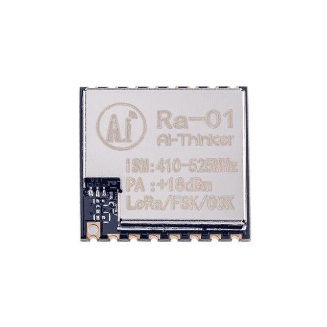
- Model: Ra-01
- Package: SMD-16 (Surface-Mount Device)
- Size: 17 x 16 x (3.2 ± 0.1) mm
- Interface: SPI
- Frequency Range: 410-525 MHz
- Max Transmit Power: 18 ± 1 dBm
- Operating Voltage: 2.5V to 3.7V (Typical: 3.3V)
- Operating Temperature: -30°C to 85°C
- Storage Environment: -40°C to 90°C, <90% relative humidity
- Antenna: Spring antenna with 2.5 dBi gain
- Weight: 0.45g
Power Consumption:
- At 433 MHz:
- TX: 93 mA
- RX: 12.15 mA
- Standby: 1.6 mA
- At 470 MHz:
- TX: 97 mA
- RX: 12.15 mA
- Standby: 1.5 mA
Receive Sensitivity:
- At 433 MHz:
- Spread Factor 7: Sensitivity of -125 dBm
- Spread Factor 10: Sensitivity of -134 dBm
- Spread Factor 12: Sensitivity of -141 dBm
- At 470 MHz:
- Spread Factor 7: Sensitivity of -126 dBm
- Spread Factor 10: Sensitivity of -135 dBm
- Spread Factor 12: Sensitivity of -141 dBm
Applications:
The Ra-01 module is particularly suited for:
- IoT Devices: Automatic meter reading, home automation, security systems, remote control systems.
- Long-Distance Communication: Remote irrigation systems and other low-power, long-distance wireless applications.
To test the Ra-01 LoRa Module with an Arduino, you can follow this procedure. I’ll guide you through wiring, installing the necessary libraries, writing the Arduino code, and performing basic communication tests.
Prerequisites:
- Hardware Required:
- Ra-01 LoRa Module (SX1278-based)
- Arduino (Uno, Nano, or similar)
- Jumper wires
- Breadboard (optional)
- Two setups (transmitter and receiver, or two Arduinos with two LoRa modules)
- Software Required:
- Arduino IDE
- LoRa library by Sandeep Mistry (
arduino-LoRalibrary)
Step 1: Wiring Connections
You will connect the Ra-01 LoRa module to the Arduino. Here’s the pin mapping for Arduino Uno:
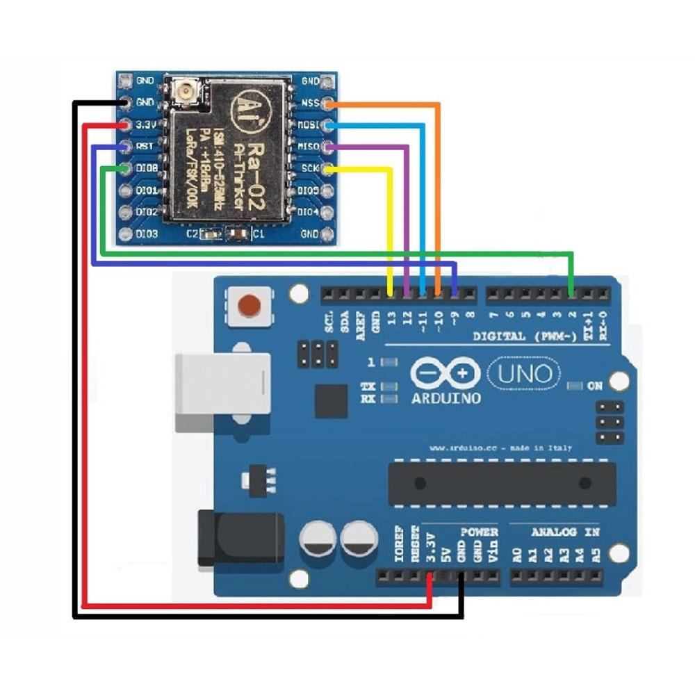
| Ra-01 Pin (SX1278) | Arduino Pin |
|---|---|
| MISO | D12 |
| MOSI | D11 |
| SCK | D13 |
| NSS (CS) | D10 |
| RST | D9 |
| DIO0 | D2 |
| 3.3V | 3.3V |
| GND | GND |
Note: Make sure you power the Ra-01 module with 3.3V, as it does not support 5V logic.
Step 2: Install LoRa Library
- Open the Arduino IDE.
- Go to Sketch → Include Library → Manage Libraries.
- In the Library Manager, search for “LoRa” by Sandeep Mistry and install it.
Step 3: Write Arduino Code for Transmitter
Here is a simple code to send a “Hello, World!” message from one Arduino with the LoRa module:
cppCopy code#include <SPI.h>
#include <LoRa.h>

#define SS 10    // NSS pin (CS)
#define RST 9    // Reset pin
#define DIO0 2   // DIO0 pin

void setup() {
  Serial.begin(9600); // Start serial communication
  while (!Serial);

  // Initialize LoRa module
  Serial.println("Initializing LoRa transmitter...");

  LoRa.setPins(SS, RST, DIO0); // Set LoRa pins

  if (!LoRa.begin(433E6)) {    // Initialize LoRa at 433 MHz
    Serial.println("Starting LoRa failed!");
    while (1);
  }

  Serial.println("LoRa initialized successfully!");
}

void loop() {
  Serial.println("Sending packet: Hello, World!");

  LoRa.beginPacket();          // Start the packet
  LoRa.print("Hello, World!");  // Add message to the packet
  LoRa.endPacket();            // End and send the packet

  delay(5000);  // Wait for 5 seconds before sending the next packet
}
Step 4: Write Arduino Code for Receiver
Here is the code for the receiver to listen and print received messages:
cppCopy code#include <SPI.h>
#include <LoRa.h>

#define SS 10    // NSS pin (CS)
#define RST 9    // Reset pin
#define DIO0 2   // DIO0 pin

void setup() {
  Serial.begin(9600); // Start serial communication
  while (!Serial);

  // Initialize LoRa module
  Serial.println("Initializing LoRa receiver...");

  LoRa.setPins(SS, RST, DIO0); // Set LoRa pins

  if (!LoRa.begin(433E6)) {    // Initialize LoRa at 433 MHz
    Serial.println("Starting LoRa failed!");
    while (1);
  }

  Serial.println("LoRa initialized successfully!");
}

void loop() {
  // Check if a packet is available
  int packetSize = LoRa.parsePacket();

  if (packetSize) {
    // Read and print the packet
    Serial.print("Received packet: ");

    while (LoRa.available()) {
      String received = LoRa.readString();
      Serial.print(received);
    }

    Serial.println();
  }
}
Step 5: Upload and Test the Code
- Upload the Transmitter Code: Upload the transmitter code to one Arduino connected to an Ra-01 module.
- Upload the Receiver Code: Upload the receiver code to another Arduino with the second Ra-01 module.
- Open Serial Monitors: Open the Serial Monitors for both Arduinos to observe communication.
- The transmitter Arduino should print “Sending packet: Hello, World!” every 5 seconds.
- The receiver Arduino should display “Received packet: Hello, World!” whenever a message is received.
Step 6: Adjust the Frequency (Optional)
The code above uses the frequency 433 MHz. Adjust the frequency in LoRa.begin(433E6) to match your module’s frequency range (e.g., 868 MHz or 915 MHz) if needed.
Step 7: Test with More Complex Data (Optional)
You can send more complex data, such as sensor readings or commands, by modifying the LoRa.print() and LoRa.readString() functions.
Troubleshooting Tips
- Ensure the Ra-01 modules are correctly powered (3.3V) and connected to the correct Arduino pins.
- Ensure the antennas are connected to the Ra-01 modules for optimal performance.
- Make sure the frequencies of both the transmitter and receiver match.
This procedure should help you test the Ra-01 LoRa module with Arduino and establish basic wireless communication between two Arduinos.
Conclusion:
The Ra-01 LoRa Module, when paired with Arduino, offers an excellent solution for long-range, low-power wireless communication. The ease of integration with the Arduino platform, combined with the power of LoRa’s spread spectrum technology, allows for the development of IoT devices that can communicate over long distances with minimal power consumption. By following the procedure outlined above, you can quickly set up a communication test and start exploring the possibilities of the Ra-01 module in your projects. Whether you’re working on remote monitoring, automation, or any IoT application, the Ra-01 provides a robust and reliable communication backbone.


