
Interfacing a 0.66-inch OLED display with Esp8266
Introduction
Simplify your OLED projects with the 0.66 inch IIC/I2C OLED Module for D1 Mini (White). Tired of the hassle of wiring and soldering only to find that your OLED still doesn’t work? Whether you are a hobbyist, creator or technology enthusiast. Dealing with these frustrations is all too familiar. That’s why we’re excited to introduce the 0.66-inch IIC/I2C OLED Module for D1 Mini (White) a game changer for your next project. In this blog post We’ll take a look at why this module is the perfect addition to your D1 Mini project and how it makes the process of integrating the display into your design easier.
Why choose a 0.66-inch OLED module for D1 Mini?
When working with a microcontroller such as the ESP8266 or D1 Mini, adding a display is often a much more painstaking task. If you’re tired: –
Messy Wiring: Endless combinations cause confusion and short circuits. – Soldering Problems: Precision work that is easy to mess up. This causes an unreliable connection.
Compatibility Issues: Your OLED does not work due to incorrect pin mapping or communication protocol. That’s the 0.66-inch OLED module you’ve been waiting for. Here’s why it stands out. –
- Plug and play simplicity No more complicated wiring diagrams and endless soldering. This OLED Module connects directly to your D1 Mini using standard I2C pins (SDA and SCL). Simply plug it into your D1 Mini. You are now ready to use. This saves a lot of time and effort. It allows you to focus on coding and creating. Header pins pre-soldered into this module make this a true plug-and-play solution. You never have to worry about connecting the wrong pins again. This often causes malfunctions or worse, fries the microcontroller.
Interfacing a 0.66-inch OLED Display with ESP8266 : A Step-by-Step Tutorial
Prerequisites :
- 1.D1 Mini V2 NodeMcu 4M Bytes Lua WIFI Internet Of Things Development Board Based ESP8266
- 2.0.66 Inch OLED Module IIC/I2C for D1 MINI (White)
- 3.solder gun
- 4.Usb to micro cable
Interfacing the oled to the D1 Mini V2 NodeMcu 4M Bytes Lua WIFI Internet Of Things Development Board Based ESP8266
D1 Mini V2 NodeMcu 4M Bytes Lua WIFI Internet Of Things Development Board Based ESP8266 Introduction :
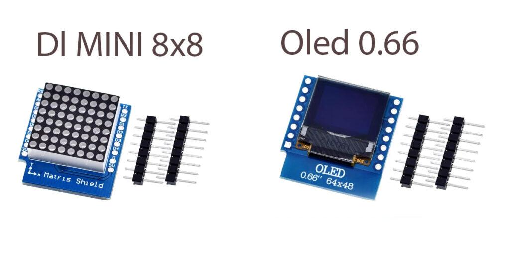
The D1 Mini V2 NodeMCU is a compact, powerful development board based on the ESP8266 microcontroller, designed for Wi-Fi-based Internet of Things (IoT) projects. It features 4MB of flash memory, making it ideal for handling complex tasks and storing larger programs or data. The ESP8266 chip at its core provides built-in Wi-Fi capabilities, allowing seamless wireless communication with other devices or cloud services.It is use many more devices as a like a matrix 8×8 matrix shield and buzzer shield
Pin Configuration :
D1 Mini V2 NodeMcu 4M Bytes Lua WIFI Internet Of Things Development Board Based ESP8266 contain the many features
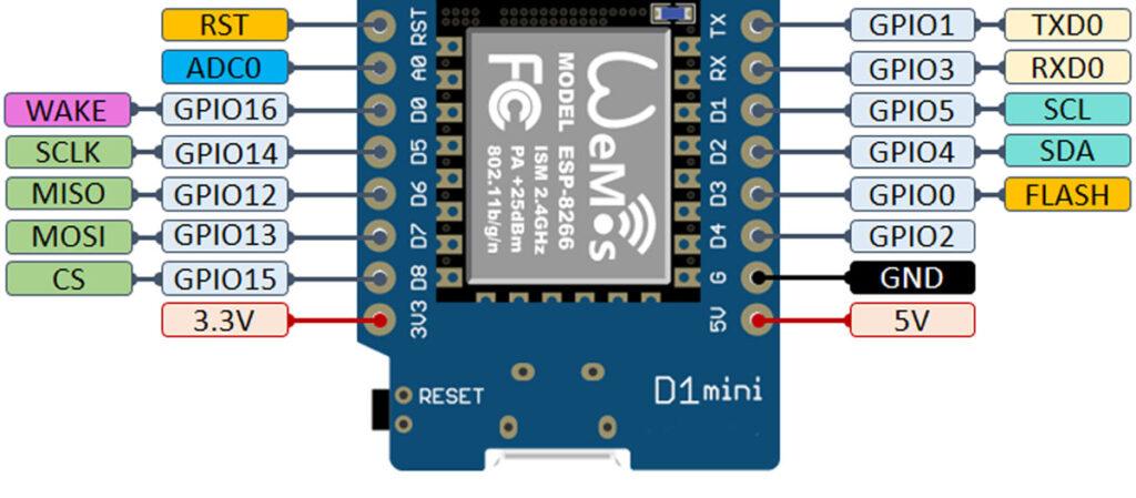
3V3 (Pin 1):
- 3.3V Power Output. This pin provides a 3.3V output that can be used to power external sensors or modules.
GND (Pin 2):
- Ground. Connect to the ground of your circuit.
D4 (Pin 3):
- GPIO2, also connected to the onboard LED.
- Used for general-purpose input/output (GPIO) and can control the onboard LED by writing to this pin (LOW = LED ON, HIGH = LED OFF).
D3 (Pin 4):
- GPIO0, also a flash button (held low during boot to enter flash mode).
- Can be used for GPIO or I2C communication (SDA).
D2 (Pin 5):
- GPIO4, a versatile GPIO pin.
- Often used for I2C communication as SCL.
D1 (Pin 6):
- GPIO5, another versatile GPIO pin.
- Typically used for I2C communication as SCL.
D0 (Pin 7):
- GPIO16, can be used as GPIO.
- Special use: Wake-up pin for deep sleep (cannot generate interrupts, and it does not support PWM or I2C).
RESET (Pin 8):
- This pin is connected to the reset button.
- Pulling this pin LOW resets the microcontroller.
GND (Pin 9):
- Another Ground pin, common with Pin 2.
TX (Pin 10):
- GPIO1, also used for UART TX (Transmit).
- When connected to USB, this pin is used for serial communication with the computer.
RX (Pin 11):
- GPIO3, also used for UART RX (Receive).
- Similar to TX, this pin handles serial communication, used to receive data from the computer.
D8 (Pin 12):
- GPIO15, can function as GPIO or SPI SS (Slave Select).
- Important: This pin must be pulled LOW during boot, which can limit its usage.
D7 (Pin 13):
- GPIO13, can be used for GPIO or SPI MOSI (Master Out Slave In).
D6 (Pin 14):
- GPIO12, can be used for GPIO or SPI MISO (Master In Slave Out).
D5 (Pin 15):
- GPIO14, can be used as GPIO or SPI SCK (Serial Clock).
D0 (Pin 16):
- GPIO16, another general-purpose pin, but often used for deep sleep wakeup functionality. This pin does not support PWM or interrupts.
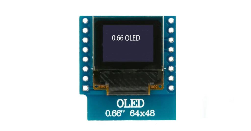
0.66 Inch OLED Module IIC/I2C for D1 MINI (White) Introduction :
0.66 Inch OLED is perfect choice for Diy projects and college product because it don’t need extra components to attached or interface you just need some solder metal and solder gun for the oled to connect with esp
Pin Configuration :
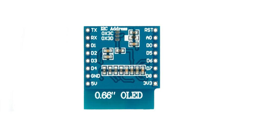
Left Side Pins:
- TX: Serial Transmission Pin (UART TX) – used for sending data over serial communication lines.
- RX: RX pin (UART RX).
- D1: GPIO pin (can be used for digital input/output purposes).
- D2: Another GPIO pin.
- D3: Digital input/output pin.
- D4: Digital input/output pin.
- GND: Common ground, connects to the ground of your power source.
- 5V: Power input pin for 5V supply.
Right Side Pins:
- RST: Reset pin, used to reset the OLED module.
- A0: Address select pin, used to configure the I2C address.
- D0: Digital input/output pin.
- D5: Another GPIO pin.
- D6: GPIO pin.
- D7: GPIO pin.
- D8: GPIO pin.
- 3V3: Power input pin for 3.3V supply.
Setting up the software
- Download and install the Arduino IDE if you haven’t already: Arduino IDE.
- Install the ESP8266 board package:
- Open Arduino IDE.
- Go to File > Preferences.
- In the Additional Boards Manager URLs, enter this URL:
http://arduino.esp8266.com/stable/package_esp8266com_index.json. - Go to Tools > Board > Boards Manager.
- Search for ESP8266 and install the ESP8266 by ESP8266 Community.
Step 1: Install Arduino IDE and ESP8266 Core
Step 2: Install Required Libraries
- Go to Sketch > Include Library > Manage Libraries.
- Search for and install the following libraries:
- Adafruit SSD1306: Used to communicate with the OLED display.
- WEMOS : For sample code.
Testing sample Code :
#include <SPI.h>
#include <Wire.h>
#include <Adafruit_GFX.h>
#include <Adafruit_SSD1306.h>

// SCL GPIO5
// SDA GPIO4
#define OLED_RESET 0  // GPIO0
Adafruit_SSD1306 display(OLED_RESET);

#define NUMFLAKES 10
#define XPOS 0
#define YPOS 1
#define DELTAY 2


#define LOGO16_GLCD_HEIGHT 16
#define LOGO16_GLCD_WIDTH  16
static const unsigned char PROGMEM logo16_glcd_bmp[] =
{ B00000000, B11000000,
  B00000001, B11000000,
  B00000001, B11000000,
  B00000011, B11100000,
  B11110011, B11100000,
  B11111110, B11111000,
  B01111110, B11111111,
  B00110011, B10011111,
  B00011111, B11111100,
  B00001101, B01110000,
  B00011011, B10100000,
  B00111111, B11100000,
  B00111111, B11110000,
  B01111100, B11110000,
  B01110000, B01110000,
  B00000000, B00110000 };

#if (SSD1306_LCDHEIGHT != 48)
#error("Height incorrect, please fix Adafruit_SSD1306.h!");
#endif

void setup()   {
  Serial.begin(9600);

  // by default, we'll generate the high voltage from the 3.3v line internally! (neat!)
  display.begin(SSD1306_SWITCHCAPVCC, 0x3C);  // initialize with the I2C addr 0x3C (for the 64x48)
  // init done

  // Show image buffer on the display hardware.
  // Since the buffer is intialized with an Adafruit splashscreen
  // internally, this will display the splashscreen.
  display.display();
  delay(2000);

  // Clear the buffer.
  display.clearDisplay();

  // draw a single pixel
  display.drawPixel(10, 10, WHITE);
  // Show the display buffer on the hardware.
  // NOTE: You must call display after making any drawing commands
  // to make them visible on the display hardware!
  display.display();
  delay(2000);
  display.clearDisplay();

  // draw many lines
  testdrawline();
  display.display();
  delay(2000);
  display.clearDisplay();

  // draw rectangles
  testdrawrect();
  display.display();
  delay(2000);
  display.clearDisplay();

  // draw multiple rectangles
  testfillrect();
  display.display();
  delay(2000);
  display.clearDisplay();

  // draw mulitple circles
  testdrawcircle();
  display.display();
  delay(2000);
  display.clearDisplay();

  // draw a white circle, 10 pixel radius
  display.fillCircle(display.width()/2, display.height()/2, 10, WHITE);
  display.display();
  delay(2000);
  display.clearDisplay();

  testdrawroundrect();
  delay(2000);
  display.clearDisplay();

  testfillroundrect();
  delay(2000);
  display.clearDisplay();

  testdrawtriangle();
  delay(2000);
  display.clearDisplay();

  testfilltriangle();
  delay(2000);
  display.clearDisplay();

  // draw the first ~12 characters in the font
  testdrawchar();
  display.display();
  delay(2000);
  display.clearDisplay();

  // draw scrolling text
  testscrolltext();
  delay(2000);
  display.clearDisplay();

  // text display tests
  display.setTextSize(1);
  display.setTextColor(WHITE);
  display.setCursor(0,0);
  display.println("Hello, world!");
  display.setTextColor(BLACK, WHITE); // 'inverted' text
  display.println(3.141592);
  display.setTextSize(2);
  display.setTextColor(WHITE);
  display.print("0x"); display.println(0xDEADBEEF, HEX);
  display.display();
  delay(2000);
  display.clearDisplay();

  // miniature bitmap display
  display.drawBitmap(30, 16,  logo16_glcd_bmp, 16, 16, 1);
  display.display();
  delay(1);

  // invert the display
  display.invertDisplay(true);
  delay(1000);
  display.invertDisplay(false);
  delay(1000);
  display.clearDisplay();

  // draw a bitmap icon and 'animate' movement
  testdrawbitmap(logo16_glcd_bmp, LOGO16_GLCD_HEIGHT, LOGO16_GLCD_WIDTH);
}


void loop() {

}


void testdrawbitmap(const uint8_t *bitmap, uint8_t w, uint8_t h) {
  uint8_t icons[NUMFLAKES][3];

  // initialize
  for (uint8_t f=0; f< NUMFLAKES; f++) {
    icons[f][XPOS] = random(display.width());
    icons[f][YPOS] = 0;
    icons[f][DELTAY] = random(5) + 1;

    Serial.print("x: ");
    Serial.print(icons[f][XPOS], DEC);
    Serial.print(" y: ");
    Serial.print(icons[f][YPOS], DEC);
    Serial.print(" dy: ");
    Serial.println(icons[f][DELTAY], DEC);
  }

  while (1) {
    // draw each icon
    for (uint8_t f=0; f< NUMFLAKES; f++) {
      display.drawBitmap(icons[f][XPOS], icons[f][YPOS], bitmap, w, h, WHITE);
    }
    display.display();
    delay(200);

    // then erase it + move it
    for (uint8_t f=0; f< NUMFLAKES; f++) {
      display.drawBitmap(icons[f][XPOS], icons[f][YPOS], bitmap, w, h, BLACK);
      // move it
      icons[f][YPOS] += icons[f][DELTAY];
      // if its gone, reinit
      if (icons[f][YPOS] > display.height()) {
        icons[f][XPOS] = random(display.width());
        icons[f][YPOS] = 0;
        icons[f][DELTAY] = random(5) + 1;
      }
    }
   }
}


void testdrawchar(void) {
  display.setTextSize(1);
  display.setTextColor(WHITE);
  display.setCursor(0,0);

  for (uint8_t i=0; i < 168; i++) {
    if (i == '\n') continue;
    display.write(i);
    if ((i > 0) && (i % 21 == 0))
      display.println();
  }
  display.display();
  delay(1);
}

void testdrawcircle(void) {
  for (int16_t i=0; i<display.height(); i+=2) {
    display.drawCircle(display.width()/2, display.height()/2, i, WHITE);
    display.display();
    delay(1);
  }
}

void testfillrect(void) {
  uint8_t color = 1;
  for (int16_t i=0; i<display.height()/2; i+=3) {
    // alternate colors
    display.fillRect(i, i, display.width()-i*2, display.height()-i*2, color%2);
    display.display();
    delay(1);
    color++;
  }
}

void testdrawtriangle(void) {
  for (int16_t i=0; i<min(display.width(),display.height())/2; i+=5) {
    display.drawTriangle(display.width()/2, display.height()/2-i,
                     display.width()/2-i, display.height()/2+i,
                     display.width()/2+i, display.height()/2+i, WHITE);
    display.display();
    delay(1);
  }
}

void testfilltriangle(void) {
  uint8_t color = WHITE;
  for (int16_t i=min(display.width(),display.height())/2; i>0; i-=5) {
    display.fillTriangle(display.width()/2, display.height()/2-i,
                     display.width()/2-i, display.height()/2+i,
                     display.width()/2+i, display.height()/2+i, WHITE);
    if (color == WHITE) color = BLACK;
    else color = WHITE;
    display.display();
    delay(1);
  }
}

void testdrawroundrect(void) {
  for (int16_t i=0; i<display.height()/2-2; i+=2) {
    display.drawRoundRect(i, i, display.width()-2*i, display.height()-2*i, display.height()/4, WHITE);
    display.display();
    delay(1);
  }
}

void testfillroundrect(void) {
  uint8_t color = WHITE;
  for (int16_t i=0; i<display.height()/2-2; i+=2) {
    display.fillRoundRect(i, i, display.width()-2*i, display.height()-2*i, display.height()/4, color);
    if (color == WHITE) color = BLACK;
    else color = WHITE;
    display.display();
    delay(1);
  }
}

void testdrawrect(void) {
  for (int16_t i=0; i<display.height()/2; i+=2) {
    display.drawRect(i, i, display.width()-2*i, display.height()-2*i, WHITE);
    display.display();
    delay(1);
  }
}

void testdrawline() {
  for (int16_t i=0; i<display.width(); i+=4) {
    display.drawLine(0, 0, i, display.height()-1, WHITE);
    display.display();
    delay(1);
  }
  for (int16_t i=0; i<display.height(); i+=4) {
    display.drawLine(0, 0, display.width()-1, i, WHITE);
    display.display();
    delay(1);
  }
  delay(250);

  display.clearDisplay();
  for (int16_t i=0; i<display.width(); i+=4) {
    display.drawLine(0, display.height()-1, i, 0, WHITE);
    display.display();
    delay(1);
  }
  for (int16_t i=display.height()-1; i>=0; i-=4) {
    display.drawLine(0, display.height()-1, display.width()-1, i, WHITE);
    display.display();
    delay(1);
  }
  delay(250);

  display.clearDisplay();
  for (int16_t i=display.width()-1; i>=0; i-=4) {
    display.drawLine(display.width()-1, display.height()-1, i, 0, WHITE);
    display.display();
    delay(1);
  }
  for (int16_t i=display.height()-1; i>=0; i-=4) {
    display.drawLine(display.width()-1, display.height()-1, 0, i, WHITE);
    display.display();
    delay(1);
  }
  delay(250);

  display.clearDisplay();
  for (int16_t i=0; i<display.height(); i+=4) {
    display.drawLine(display.width()-1, 0, 0, i, WHITE);
    display.display();
    delay(1);
  }
  for (int16_t i=0; i<display.width(); i+=4) {
    display.drawLine(display.width()-1, 0, i, display.height()-1, WHITE);
    display.display();
    delay(1);
  }
  delay(250);
}

void testscrolltext(void) {
  display.setTextSize(2);
  display.setTextColor(WHITE);
  display.setCursor(10,0);
  display.clearDisplay();
  display.println("scroll");
  display.display();
  delay(1);

  display.startscrollright(0x00, 0x0F);
  delay(2000);
  display.stopscroll();
  delay(1000);
  display.startscrollleft(0x00, 0x0F);
  delay(2000);
  display.stopscroll();
  delay(1000);
  display.startscrolldiagright(0x00, 0x07);
  delay(2000);
  display.startscrolldiagleft(0x00, 0x07);
  delay(2000);
  display.stopscroll();
}
Step 4: Upload the Code
- Select the board:
- Go to Tools > Board > ESP8266 Boards and select LOLIN(WEMOS) D1 mini (clone).
- Select the correct port:
- Go to Tools > Port and select the port that your D1 Mini is connected to.
- Click the Upload button in the Arduino IDE to upload the code to your D1 Mini.
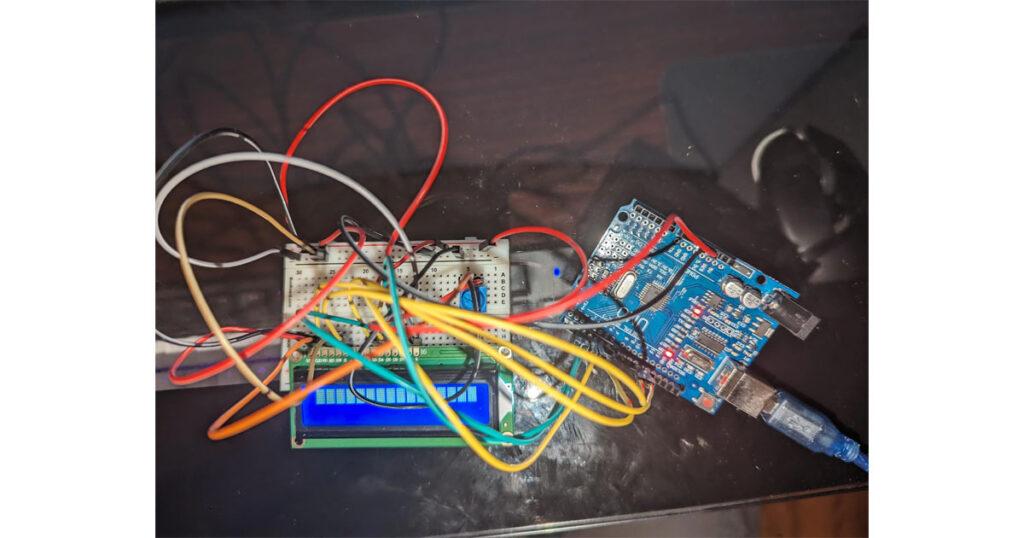
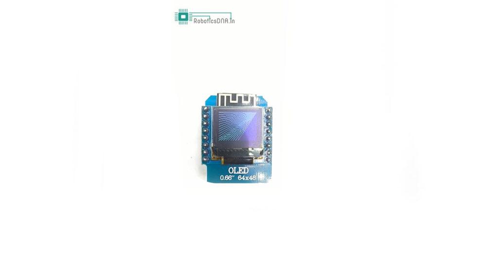
Results:
Conclusion :
The 0.66-inch IIC/I2C OLED Module for the D1 Mini is a must-have for makers, hobbyists, and IoT enthusiasts looking to add a compact and efficient display to their projects without the usual headaches of complicated wiring and compatibility issues. Its plug-and-play design, coupled with its ease of use, simplifies the integration process and frees you from the frustrations of messy soldering or incorrect connections. Paired with the powerful and versatile D1 Mini ESP8266, this OLED module opens up a world of possibilities for creating visually appealing and interactive IoT applications.
By following the step-by-step guide provided, you’ll be able to set up and code your own display with minimal effort, allowing you to focus on building more advanced features and experimenting with various designs. Whether you’re displaying sensor data, text, or graphics, this OLED module is a fantastic addition to your toolkit, making your next project not only easier but also more polished and professional. Happy building!


