
Monitor Water Tank Level with GSM & ESP8266 on Blynk
Overview :
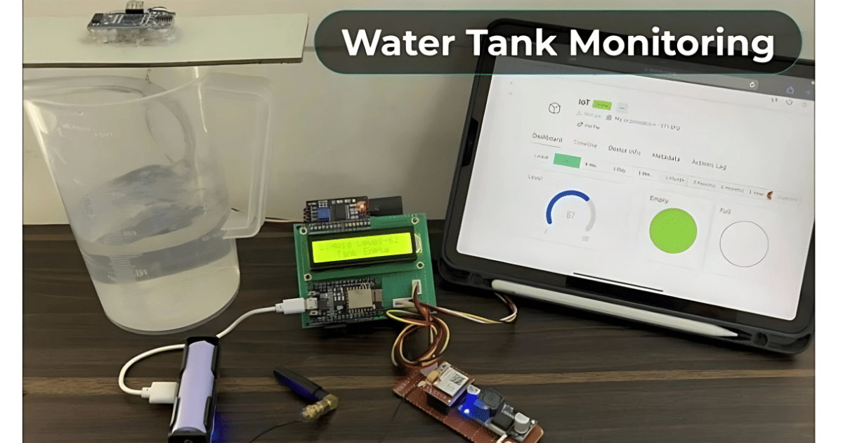
In this project, we will develop an IoT-based Water Tank Level Monitoring System that utilizes the GSM/GPRS network to monitor Water Level. By incorporating the SIM800L GSM Module with ESP8266 Microcontroller, this system is designed to transmit the water tank’s level data directly to the Blynk Dashboard. The user-friendly dashboard will not only display the current water level but also indicate whether the tank is full or empty. This will provide users with real-time insights into their water storage system.
Furthermore, the project enhances user convenience by offering the capability to receive updates on the tank’s status through SMS. This means that in addition to the dashboard’s visual representation of the water level, users can also get notified of the tank being full or empty via text messages. For measuring the Water Level, we will use the Ultrasonic Sensor HC-SR04.
Bill of Materials :
Following are the list of components required to build Water Tank Level Monitoring System with GSM & ESP8266 on Blynk.
ESP8266 Wi-Fi Module
- The ESP8266 will be used to connect the system to the internet, allowing it to send data to the Blynk app on your phone.
Water Level Sensor (Ultrasonic or Float Sensor)
- Ultrasonic Sensor (e.g., HC-SR04): It will measure the water level in the tank by emitting sound waves and measuring the time it takes for the waves to bounce back.
LCD Display (e.g., 16×2 LCD with I2C Module)
- The LCD will display the current water level, making it easy to visually monitor the tank level in addition to the data sent to the Blynk app.
GSM Module (e.g., SIM800L)
- The GSM module will allow you to send SMS alerts when certain conditions are met (such as when the tank is full or empty). It works through a mobile network, so no Wi-Fi is needed for SMS functionality.
Blynk App & Blynk Library
- The Blynk app will allow you to visualize the water tank level and receive real-time updates on your phone. The ESP8266 will communicate with the Blynk cloud server.
- You’ll need the Blynk library installed in your Arduino IDE to interface with the Blynk app.
Power Supply
- You’ll need a suitable power supply for the ESP8266 and GSM module. For example, the ESP8266 requires 3.3V and can draw significant current when connecting to Wi-Fi, while the GSM module needs a 5V supply.
Jumper Wires and Breadboard
- For connecting the components like the ESP8266, sensors, and GSM module together.
Resistors, Transistors, or MOSFETs
Circuit Diagram & Setup :
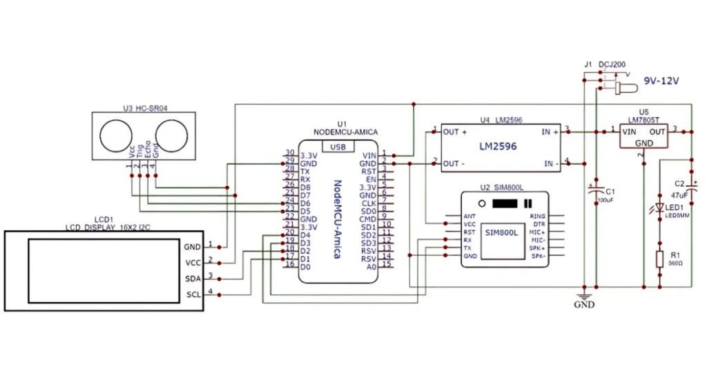
Here is the circuit for Water Tank Level Monitoring System with GSM & ESP8266. All the active-passive components are connected to the digital pins of NodeMCU ESP8266 Board.
The center of the Circuit is NodeMCU Board which works on 5V power supply. The 5V input is fed to NodeMCU board via 7805 Voltage regulator IC. The Ultrasonic Sensor HC-SR04 is connected to the digital pins of NodeMCU ESP8266 Board.
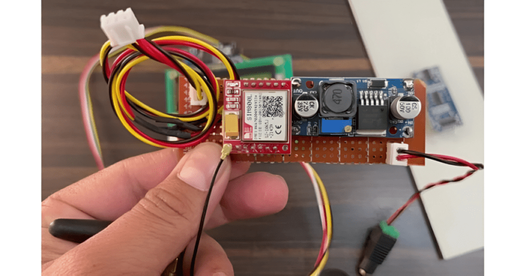
For the GSM power supply part we are using the Buck Converter Module LM2596. The LM2596 is supplied with 9V DC Supply. The LM2596 output is setup between 3.7V to 4V for GSM Module. The 16X2 I2C LCD Display is connected to I2C Pins of NodemCU ESP8266 Board.
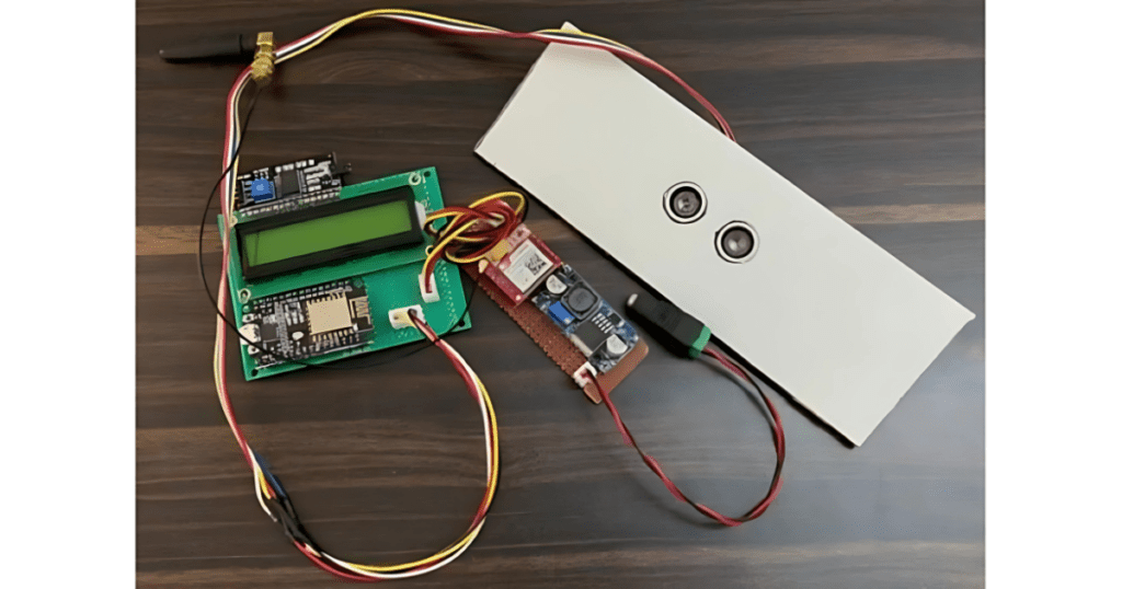
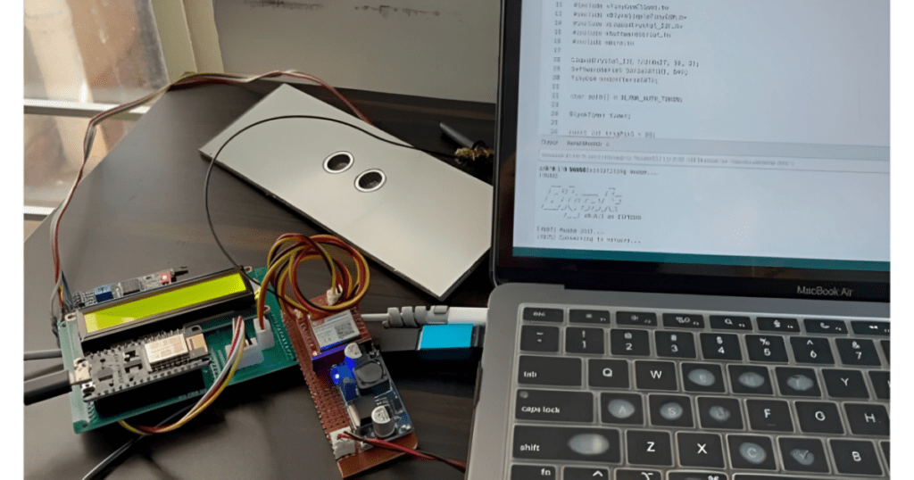
For the demo, I assembled the project on a Zero PCB Board here. You can also assemble the circuit on a breadboard or Vero board or use your own custom PCB for commercial applications.
Setting up Blynk Dashboard :
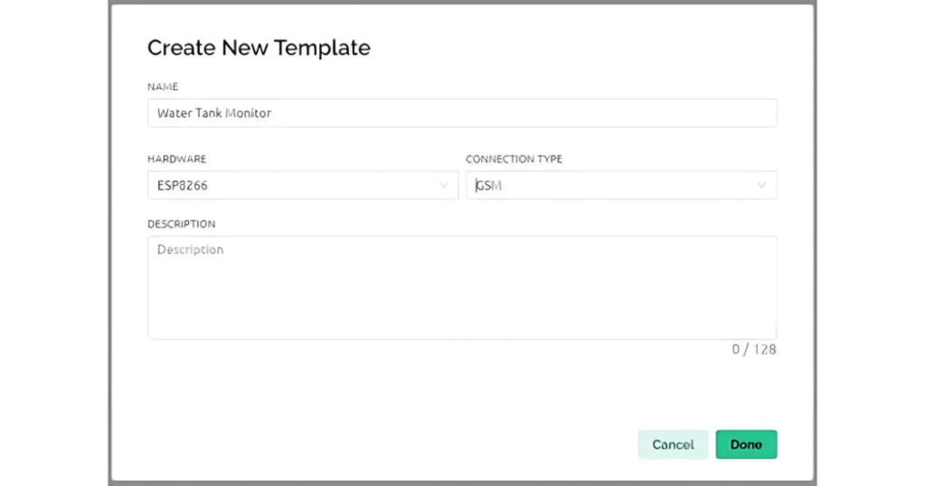
Let’s begin by setting up the Blynk App for data visualization. First, create a template and assign it any name of your choosing.
For the hardware selection, choose ESP8266, and set the connection type to GSM.
Next, navigate to the web dashboard. Here, you’ll need to drag and drop one gauge widget and two LED widgets onto the dashboard. Once added, adjust their sizes for better visibility and provide them with appropriate titles.
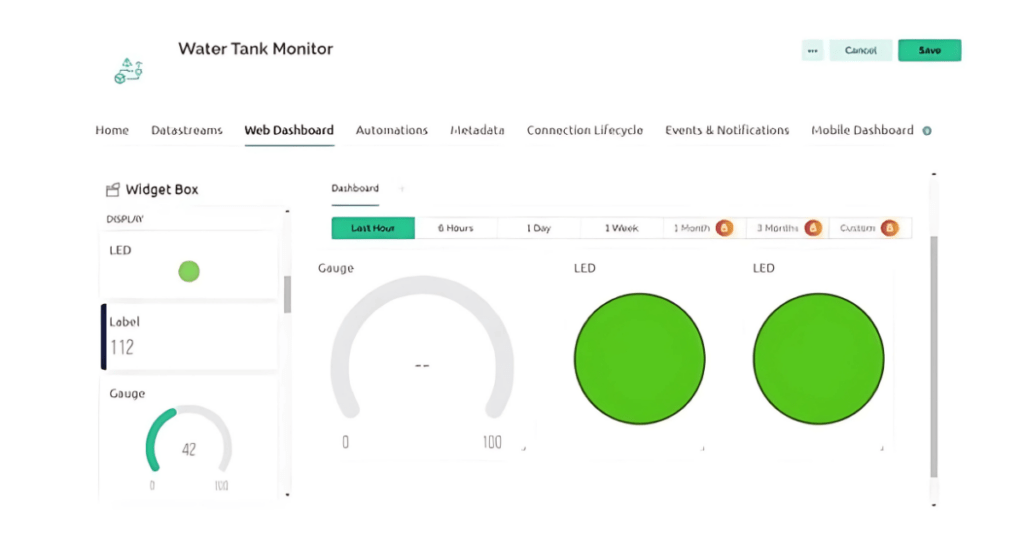
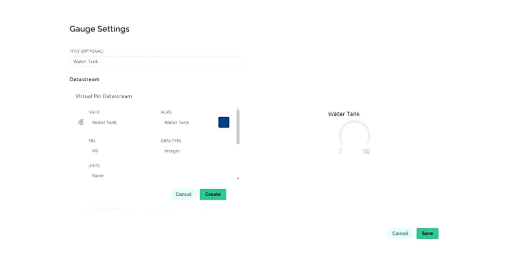
You’ll also need to create data streams that handle integer values ranging from 0 to 100% to represent your data accurately. For the LED widgets, assign values of 1 and 0 to signify ‘tank full’ and ‘tank empty’ statuses, respectively.
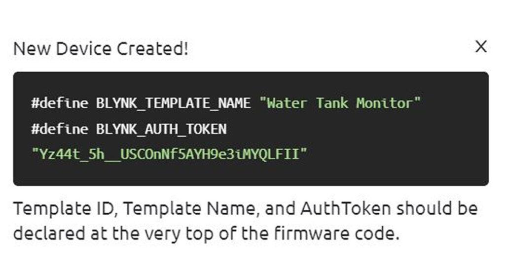
Following this, create a device, giving it any name you prefer. Upon completion, you will observe that the device has been successfully created on the platform.
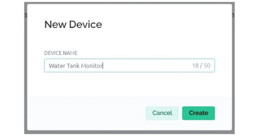
Additionally, you’ll be provided with credentials that are crucial for this project.
Source Code/Program
The code is designed for a GSM Water Tank Monitoring System using GSM module (SIM800), ESP8266 Microcontroller and an ultrasonic sensor to measure the liquid level in a tank. It connects to the Blynk IoT platform for remote monitoring and control. The system displays the liquid level on an LCD screen and sends alerts via SMS when the tank is full or empty.
It utilizes the Blynk library for communication with the Blynk app, the TinyGsmClient library for GSM functionality, and controls an ultrasonic sensor to determine the tank’s liquid level. Additionally, it includes functions to send SMS alerts for specific tank level conditions.
Add the following libraries to the Arduino folder, before uploading the code.
1. TinyGSM Client Library: Download TinyGsmClient Library
2. Blynk Library: Download Blynk Library
3. I2C LCD Library: Download I2C_LCD Library
From this line, change the Blynk Authentication token and replace it with your Blynk token.
1
#define BLYNK_AUTH_TOKEN "*************************"
You need to replace the apn in this line with the APN Service provider of your Cellular network.
char apn[] = "internet";In the SendMessage2 & SendMessage1 function, replace the number where you want to send the SMS for water alert.
SerialAT.println("AT+CMGS=\"+91xxxxxxxx\"\r");Here is the full code for this project.
#define BLYNK_TEMPLATE_ID "TMPL30BL34-7r"
#define BLYNK_TEMPLATE_NAME "IoT"
#define BLYNK_AUTH_TOKEN "*************************"

#define BLYNK_PRINT Serial
#define TINY_GSM_MODEM_SIM800

char apn[] = "internet";
char user[] = "";
char pass[] = "";

#include <TinyGsmClient.h>
#include <BlynkSimpleTinyGSM.h>
#include <LiquidCrystal_I2C.h>
#include <SoftwareSerial.h>
#include <Wire.h>

LiquidCrystal_I2C lcd(0x27, 16, 2);
SoftwareSerial SerialAT(D3, D4); //gsm
TinyGsm modem(SerialAT);

char auth[] = BLYNK_AUTH_TOKEN;

BlynkTimer timer;

const int trigPin1 = D5;
const int echoPin1 = D6;
unsigned long startMillis;
unsigned long currentMillis;
const unsigned long period = 10000;
long duration1;
int distance1;

int firstmessageSent = 0;
int secondmessageSent = 0;

void setup() {

  Serial.begin(9600);
  delay(10);
  SerialAT.begin(9600);
  delay(3000);
  Serial.println("Initializing modem...");
  modem.restart();
  Blynk.begin(auth, modem, apn, user, pass);
  Wire.begin(D2, D1);
  lcd.init();
  lcd.backlight();
  lcd.setCursor(0, 0);
  lcd.print("   WELCOME TO");
  lcd.setCursor(0, 1);
  lcd.print("  OUR PROJECTS");
  delay(2000);
  lcd.clear();
  lcd.setCursor(0, 0);
  lcd.print(" SMART");
  lcd.setCursor(0, 1);
  lcd.print("TANK MONITORING");
  delay(3000);
  lcd.clear();
  pinMode(trigPin1, OUTPUT);
  pinMode(echoPin1, INPUT);
}
void loop() {

  ultersonic();
  lcd.clear();
  lcd.setCursor(0, 0);
  lcd.print("Liquid Level-");
  lcd.print(distance1);
  Blynk.virtualWrite(V0, distance1);

  if (distance1 < 20) {
    digitalWrite(D0, HIGH);
    digitalWrite(D8, LOW);
    lcd.setCursor(0, 1);
    lcd.print("   Tank Full.");
    WidgetLED LED(V2);
    LED.on();
    WidgetLED LED1(V1);
    LED1.off();
    if (secondmessageSent == 0) {
      SendMessage1();
      secondmessageSent = 1;
      firstmessageSent = 0;
    }
    delay(100);
  }

  if (distance1 > 60) {
    digitalWrite(D0, HIGH);
    digitalWrite(D8, LOW);
    lcd.setCursor(0, 1);
    lcd.print("   Tank Empty");

    if (firstmessageSent == 0) {
      SendMessage2();
      secondmessageSent = 0;
      firstmessageSent = 1;
    }
    delay(100);
  } else {
    digitalWrite(D0, HIGH);
    digitalWrite(D8, LOW);
    WidgetLED LED(V2);
    LED.off();
    WidgetLED LED1(V1);
    LED1.on();
  }
  currentMillis = millis();
  if (currentMillis - startMillis >= period) {
    startMillis = currentMillis;
  }
}

void SendMessage2() {
  SerialAT.println(" Tank Empty ");
  SerialAT.println("AT+CMGF=1");
  delay(1000);
  SerialAT.println("AT+CMGS=\"+91xxxxxxxx\"\r");
  delay(1000);
  SerialAT.println(" Tank Empty");
  delay(100);
  SerialAT.println((char)26);
  delay(1000);
}

void SendMessage1() {
  SerialAT.println(" Tank Full ");
  SerialAT.println("AT+CMGF=1");
  delay(1000);
  SerialAT.println("AT+CMGS=\"+91xxxxxxxxxx\"\r");
  delay(1000);
  SerialAT.println(" Tank Full ");
  delay(100);
  SerialAT.println((char)26);
  delay(1000);
}

void ultersonic() {
  digitalWrite(trigPin1, LOW);
  delayMicroseconds(2);
  digitalWrite(trigPin1, HIGH);
  delayMicroseconds(10);
  digitalWrite(trigPin1, LOW);
  duration1 = pulseIn(echoPin1, HIGH);
  distance1 = duration1 * 0.207 / 2;
  Serial.println(distance1);
  delay(100);
}
Working of Water Tank Level Monitor with GSM & ESP8266 on Blynk :
After uploading the code, the device is ready for testing. Initially, the GSM module establishes a connection with the Blynk Server, indicating the system is ready for testing.
To initiate testing, the water pump is activated to start filling the tank.
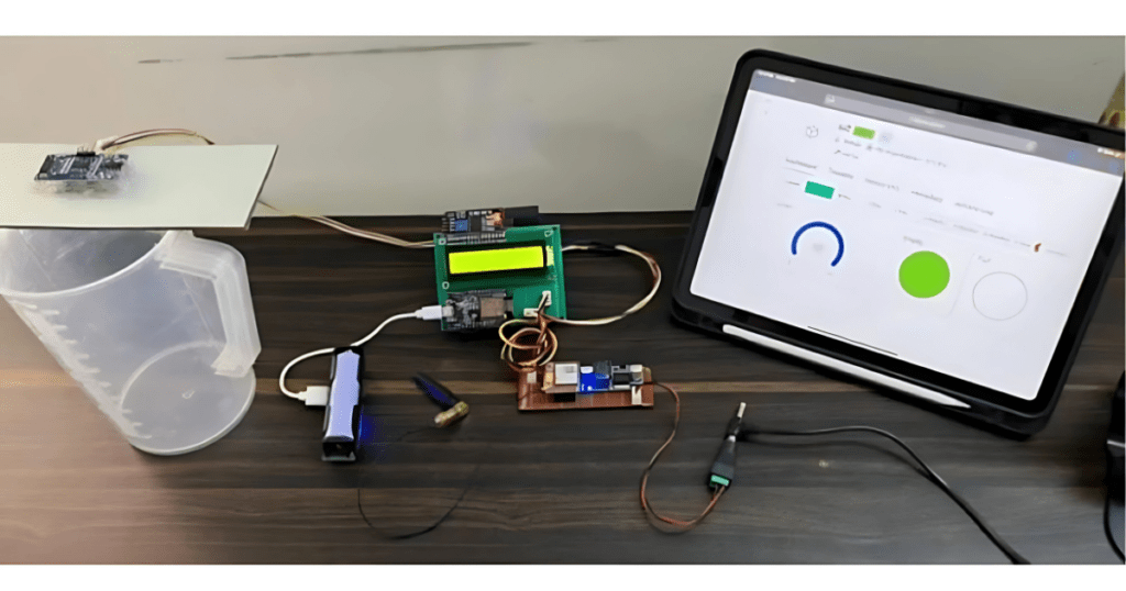
During this process, the Blynk Dashboard’s gauge visually represents the decreasing level of emptiness, indicating the tank is gradually being filled with water. This change is gradual, mirroring the actual filling process of the tank.
Once the tank reaches full capacity, the dashboard indicator changes to red, signifying that the tank is completely full.
Additionally, the LCD display connected to the system provides real-time updates on the water level.
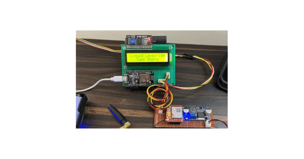
Initially, it shows the liquid level at 100 and indicates that the tank is empty. Correspondingly, a notification is sent as an SMS to the phone, confirming that the tank is empty.
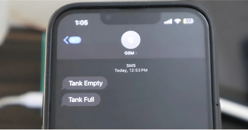
The final phase of the test involves filling the tank to observe the system’s response to a full tank scenario. As the tank becomes full, the LCD display updates to indicate that the tank is full, and a matching SMS notification is sent to the phone, confirming the tank’s full status.