
How RFID Works and How To Make an Arduino based RFID Door Lock

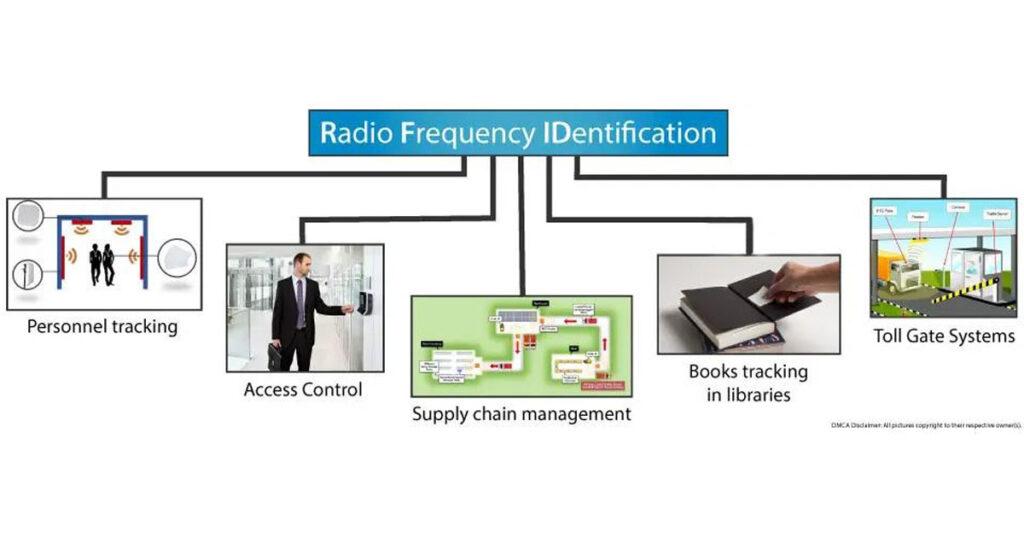
RFID stands for Radio Frequency IDentification and it’s a non-contact technology that’s broadly used in many industries for tasks such as personnel tracking, access control, supply chain management, books tracking in libraries, tollgate systems and so on.
How RFID Works
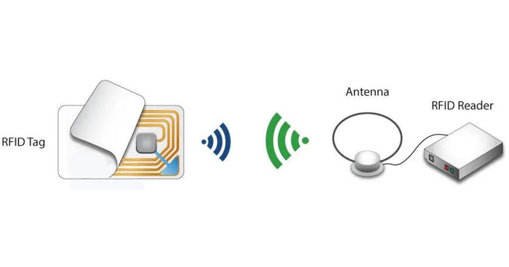
An RFID system consists of two main components, a transponder or a tag which is located on the object that we want to be identified, and a transceiver or a reader.
The RFID reader consist of a radio frequency module, a control unit and an antenna coil which generates high frequency electromagnetic field. On the other hand, the tag is usually a passive component, which consist of just an antenna and an electronic microchip, so when it gets near the electromagnetic field of the transceiver, due to induction, a voltage is generated in its antenna coil and this voltage serves as power for the microchip.
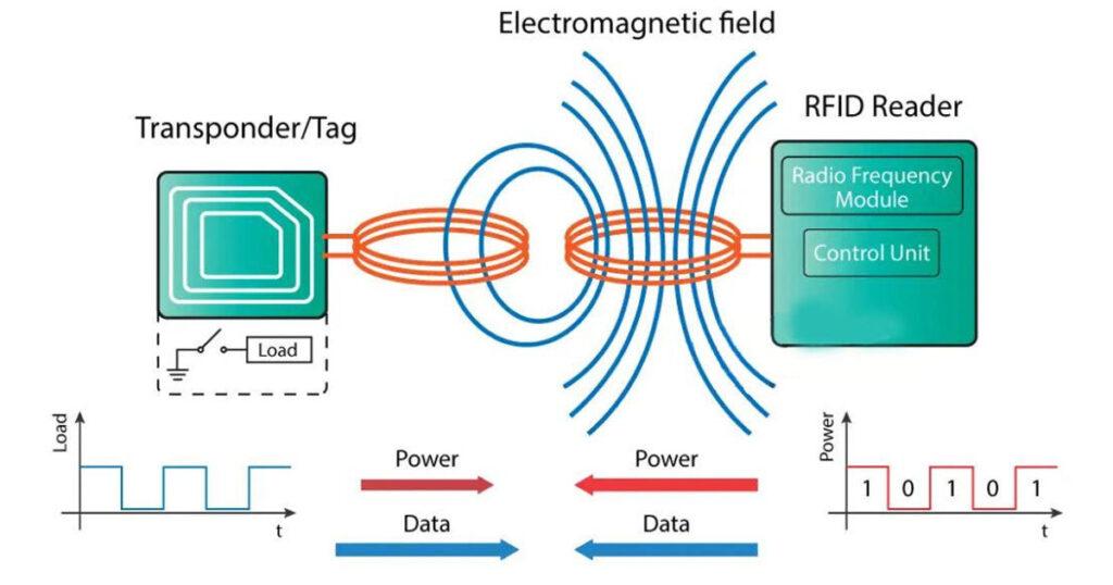
Now as the tag is powered it can extract the transmitted message from the reader, and for sending message back to the reader, it uses a technique called load manipulation. Switching on and off a load at the antenna of the tag will affect the power consumption of the reader’s antenna which can be measured as voltage drop. This changes in the voltage will be captured as ones and zeros and that’s the way the data is transferred from the tag to the reader.
There’s also another way of data transfer between the reader and the tag, called backscattered coupling. In this case, the tag uses part of the received power for generating another electromagnetic field which will be picked up by the reader’s antenna.
RFID and Arduino
So that’s the basic working principle and now let’s see how we can use RFID with Arduino and build our own RFID door lock. We will use tags that are based on the MIFARE protocol and the MFRC522 RFID reader, which cost just a couple of dollars.

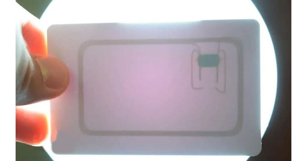
These tags have 1kb of memory and have a microchip that can do arithmetic operations. Their operating frequency is 13.56 MHz and the operating distance is up to 10 cm depending on the geometry of antenna. If we bring one of these tags in front of a light source we can notice the antenna and the microchip that we previously talked about.
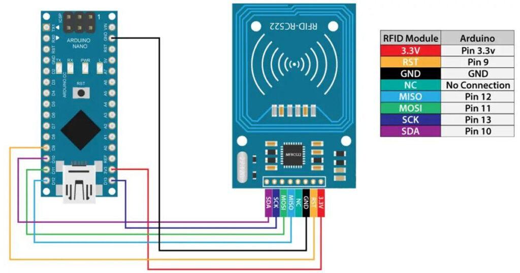
As for the RFID reader module, it uses the SPI protocol for communication with the Arduino board and here’s how we need to connect them. Please note that we must connect the VCC of the module to 3.3V and as for the other pins we don’t have to worry as they are 5V tolerant.
Once we connect the module we need to download the MFRC522 library from GitHub. The library comes with several good examples from which we can learn how to use the module.
First we can upload the “DumpInfo” example and test whether our system works properly. Now if we run the Serial Monitor and bring the tag near the module, the reader will start reading the tag and all information from the tag will be displayed on the serial monitor.

Here we can notice the UID number of the tag as well as the 1 KB of memory which is actually divided into 16 sectors, each sector into 4 blocks and each block can store 2 bytes of data. For this tutorial we won’t use any of the tag’s memory, we will just use the UID number of the tag.
Arduino RFID Door Lock Access Control Project
Before we go through the code of our RFID door lock project, let’s take a look at the components and the circuit schematics of this project.
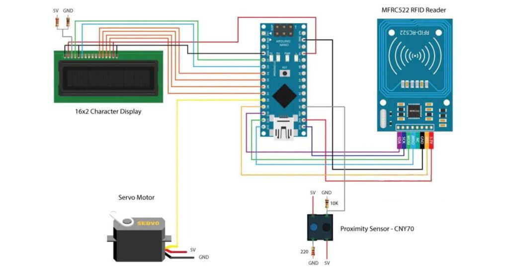
In addition to the RFID module we will use a proximity sensor for checking whether the door is closed or opened, a servo motor for the lock mechanism and a character display.
The project has the following workflow: First we have to set a master tag and then the system goes into normal mode. If we scan an unknown tag the access will be denied, but if we scan the master we will enter a program mode from where we can add and authorize the unknown tag. So now if we scan the tag again the access will be granted so we can open the door.

The door will automatically lock after we will close the door. If we want to remove a tag from the system we just have to go again into program mode, scan the know tag and it will be removed.
Source Code
Now let’s take a look at the code. So first we need to include the libraries for the RFID module, the display and the servo motor, define some variables needed for the program below as well as create the instances of the libraries.
#include <SPI.h>
#include <MFRC522.h>
#include <LiquidCrystal.h>
#include <Servo.h>

#define RST_PIN   9
#define SS_PIN    10

byte readCard[4];
char* myTags[100] = {};
int tagsCount = 0;
String tagID = "";
boolean successRead = false;
boolean correctTag = false;
int proximitySensor;
boolean doorOpened = false;

// Create instances
MFRC522 mfrc522(SS_PIN, RST_PIN);
LiquidCrystal lcd(2, 3, 4, 5, 6, 7); //Parameters: (rs, enable, d4, d5, d6, d7)
Servo myServo; // Servo motor
In the setup section, first we initialize the modules, and set the initial value of the servo motor into a lock position. Then we print the initial message to the display and with the following “while” loop we wait until a master tag is scanned. The getID() custom function gets the tag UID and we put it into the first location of the myTags[0] array.
void setup() {
  // Initiating
  SPI.begin();        // SPI bus
  mfrc522.PCD_Init(); //  MFRC522
  lcd.begin(16, 2);   // LCD screen
  myServo.attach(8);  // Servo motor

  myServo.write(10); // Initial lock position of the servo motor
  // Prints the initial message
  lcd.print("-No Master Tag!-");
  lcd.setCursor(0, 1);
  lcd.print("    SCAN NOW");
  // Waits until a master card is scanned
  while (!successRead) {
    successRead = getID();
    if ( successRead == true) {
      myTags[tagsCount] = strdup(tagID.c_str()); // Sets the master tag into position 0 in the array
      lcd.clear();
      lcd.setCursor(0, 0);
      lcd.print("Master Tag Set!");
      tagsCount++;
    }
  }
  successRead = false;
  printNormalModeMessage();
}
Let’s take a look at the getID() custom function. First it checks whether there is a new tag placed near the reader and if so we will continue to the “for” loop which will get the UID of the tag. The tags that we are using have 4 byte UID number so that’s why we need to do 4 iterations with this loop, and using the concat() function we add the 4 bytes into a single String variable. We also set all characters of the string to upper cases and the end we stop the reading.
uint8_t getID() {
  // Getting ready for Reading PICCs
  if ( ! mfrc522.PICC_IsNewCardPresent()) { //If a new PICC placed to RFID reader continue
    return 0;
  }
  if ( ! mfrc522.PICC_ReadCardSerial()) {   //Since a PICC placed get Serial and continue
    return 0;
  }
  tagID = "";
  for ( uint8_t i = 0; i < 4; i++) {  // The MIFARE PICCs that we use have 4 byte UID
    readCard[i] = mfrc522.uid.uidByte[i];
    tagID.concat(String(mfrc522.uid.uidByte[i], HEX)); // Adds the 4 bytes in a single String variable
  }
  tagID.toUpperCase();
  mfrc522.PICC_HaltA(); // Stop reading
  return 1;
}
Before we enter the main loop, at the end of the setup section, we also call the printNormalModeMessage() custom function which prints the “Access Control” message on the display.
void printNormalModeMessage() {
  delay(1500);
  lcd.clear();
  lcd.print("-Access Control-");
  lcd.setCursor(0, 1);
  lcd.print(" Scan Your Tag!");
}
In the main loop we start with reading the value of the proximity sensor, which tell us whether the door is closed or not.
int proximitySensor = analogRead(A0);So if the door is closed, using the same lines as we described in the getID() custom function we will scan and get the UID of the new tag. We can notice here that the code won’t proceed any further until we scan a tag because of the “return” lines in the “if” statements.
Once we have the tag scanned we check whether that tag is the master that that we previously registered, and if that’s true we will enter the program mode. In this mode if we scan an already authorized tag it will be removed from the system, or if the tag is unknown it will be added to the system as authorized.
/ Checks whether the scanned tag is the master tag
    if (tagID == myTags[0]) {
      lcd.clear();
      lcd.print("Program mode:");
      lcd.setCursor(0, 1);
      lcd.print("Add/Remove Tag");
      while (!successRead) {
        successRead = getID();
        if ( successRead == true) {
          for (int i = 0; i < 100; i++) {
            if (tagID == myTags[i]) {
              myTags[i] = "";

              lcd.clear();
              lcd.setCursor(0, 0);
              lcd.print("  Tag Removed!");
              printNormalModeMessage();
              return;
            }
          }
          myTags[tagsCount] = strdup(tagID.c_str());
          lcd.clear();
          lcd.setCursor(0, 0);
          lcd.print("   Tag Added!");
          printNormalModeMessage();
          tagsCount++;
          return;
        }
      }
    }
Outside the program mode, with the next “for” loop we check whether the scanned tag is equal to any of the registered tags and we either unlock the door or keep the access denied. At the end in the “else” statement we wait until the door is closed, then we lock the door and print the normal mode message again.
// Checks whether the scanned tag is authorized
    for (int i = 0; i < 100; i++) {
      if (tagID == myTags[i]) {
        lcd.clear();
        lcd.setCursor(0, 0);
        lcd.print(" Access Granted!");
        myServo.write(170); // Unlocks the door
        printNormalModeMessage();
        correctTag = true;
      }
    }
    if (correctTag == false) {
      lcd.clear();
      lcd.setCursor(0, 0);
      lcd.print(" Access Denied!");
      printNormalModeMessage();
    }
  }
  // If door is open...
  else {
    lcd.clear();
    lcd.setCursor(0, 0);
    lcd.print(" Door Opened!");
    while (!doorOpened) {
      proximitySensor = analogRead(A0);
      if (proximitySensor > 200) {
        doorOpened = true;
      }
    }
    doorOpened = false;
    delay(500);
    myServo.write(10); // Locks the door
    printNormalModeMessage();
  }
So that’s pretty much everything and here’s the complete code of the project:
* Library: MFRC522, https://github.com/miguelbalboa/rfid
*/

#include <SPI.h>
#include <MFRC522.h>
#include <LiquidCrystal.h>
#include <Servo.h>

#define RST_PIN   9
#define SS_PIN    10

byte readCard[4];
char* myTags[100] = {};
int tagsCount = 0;
String tagID = "";
boolean successRead = false;
boolean correctTag = false;
int proximitySensor;
boolean doorOpened = false;

// Create instances
MFRC522 mfrc522(SS_PIN, RST_PIN);
LiquidCrystal lcd(2, 3, 4, 5, 6, 7); //Parameters: (rs, enable, d4, d5, d6, d7)
Servo myServo; // Servo motor

void setup() {
  // Initiating
  SPI.begin();        // SPI bus
  mfrc522.PCD_Init(); //  MFRC522
  lcd.begin(16, 2);   // LCD screen
  myServo.attach(8);  // Servo motor

  myServo.write(10); // Initial lock position of the servo motor
  // Prints the initial message
  lcd.print("-No Master Tag!-");
  lcd.setCursor(0, 1);
  lcd.print("    SCAN NOW");
  // Waits until a master card is scanned
  while (!successRead) {
    successRead = getID();
    if ( successRead == true) {
      myTags[tagsCount] = strdup(tagID.c_str()); // Sets the master tag into position 0 in the array
      lcd.clear();
      lcd.setCursor(0, 0);
      lcd.print("Master Tag Set!");
      tagsCount++;
    }
  }
  successRead = false;
  printNormalModeMessage();
}

void loop() {
  int proximitySensor = analogRead(A0);
  // If door is closed...
  if (proximitySensor > 200) {
    if ( ! mfrc522.PICC_IsNewCardPresent()) { //If a new PICC placed to RFID reader continue
      return;
    }
    if ( ! mfrc522.PICC_ReadCardSerial()) {   //Since a PICC placed get Serial and continue
      return;
    }
    tagID = "";
    // The MIFARE PICCs that we use have 4 byte UID
    for ( uint8_t i = 0; i < 4; i++) {  //
      readCard[i] = mfrc522.uid.uidByte[i];
      tagID.concat(String(mfrc522.uid.uidByte[i], HEX)); // Adds the 4 bytes in a single String variable
    }
    tagID.toUpperCase();
    mfrc522.PICC_HaltA(); // Stop reading

    correctTag = false;
    // Checks whether the scanned tag is the master tag
    if (tagID == myTags[0]) {
      lcd.clear();
      lcd.print("Program mode:");
      lcd.setCursor(0, 1);
      lcd.print("Add/Remove Tag");
      while (!successRead) {
        successRead = getID();
        if ( successRead == true) {
          for (int i = 0; i < 100; i++) {
            if (tagID == myTags[i]) {
              myTags[i] = "";
              lcd.clear();
              lcd.setCursor(0, 0);
              lcd.print("  Tag Removed!");
              printNormalModeMessage();
              return;
            }
          }
          myTags[tagsCount] = strdup(tagID.c_str());
          lcd.clear();
          lcd.setCursor(0, 0);
          lcd.print("   Tag Added!");
          printNormalModeMessage();
          tagsCount++;
          return;
        }
      }
    }
    successRead = false;
    // Checks whether the scanned tag is authorized
    for (int i = 0; i < 100; i++) {
      if (tagID == myTags[i]) {
        lcd.clear();
        lcd.setCursor(0, 0);
        lcd.print(" Access Granted!");
        myServo.write(170); // Unlocks the door
        printNormalModeMessage();
        correctTag = true;
      }
    }
    if (correctTag == false) {
      lcd.clear();
      lcd.setCursor(0, 0);
      lcd.print(" Access Denied!");
      printNormalModeMessage();
    }
  }
  // If door is open...
  else {
    lcd.clear();
    lcd.setCursor(0, 0);
    lcd.print(" Door Opened!");
    while (!doorOpened) {
      proximitySensor = analogRead(A0);
      if (proximitySensor > 200) {
        doorOpened = true;
      }
    }
    doorOpened = false;
    delay(500);
    myServo.write(10); // Locks the door
    printNormalModeMessage();
  }
}

uint8_t getID() {
  // Getting ready for Reading PICCs
  if ( ! mfrc522.PICC_IsNewCardPresent()) { //If a new PICC placed to RFID reader continue
    return 0;
  }
  if ( ! mfrc522.PICC_ReadCardSerial()) {   //Since a PICC placed get Serial and continue
    return 0;
  }
  tagID = "";
  for ( uint8_t i = 0; i < 4; i++) {  // The MIFARE PICCs that we use have 4 byte UID
    readCard[i] = mfrc522.uid.uidByte[i];
    tagID.concat(String(mfrc522.uid.uidByte[i], HEX)); // Adds the 4 bytes in a single String variable
  }
  tagID.toUpperCase();
  mfrc522.PICC_HaltA(); // Stop reading
  return 1;
}

void printNormalModeMessage() {
  delay(1500);
  lcd.clear();
  lcd.print("-Access Control-");
  lcd.setCursor(0, 1);
  lcd.print(" Scan Your Tag!");
}