How to Control Servo Motors with Arduino – Complete Guide
What is Servo Motor?
A servo motor is a closed-loop system that uses position feedback to control its motion and final position. There are many types of servo motors and their main feature is the ability to precisely control the position of their shaft.
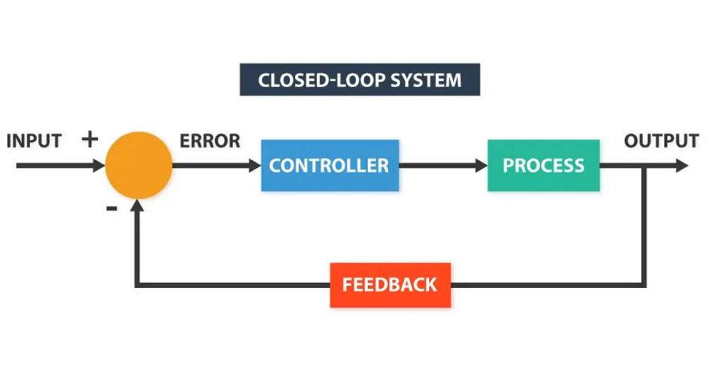
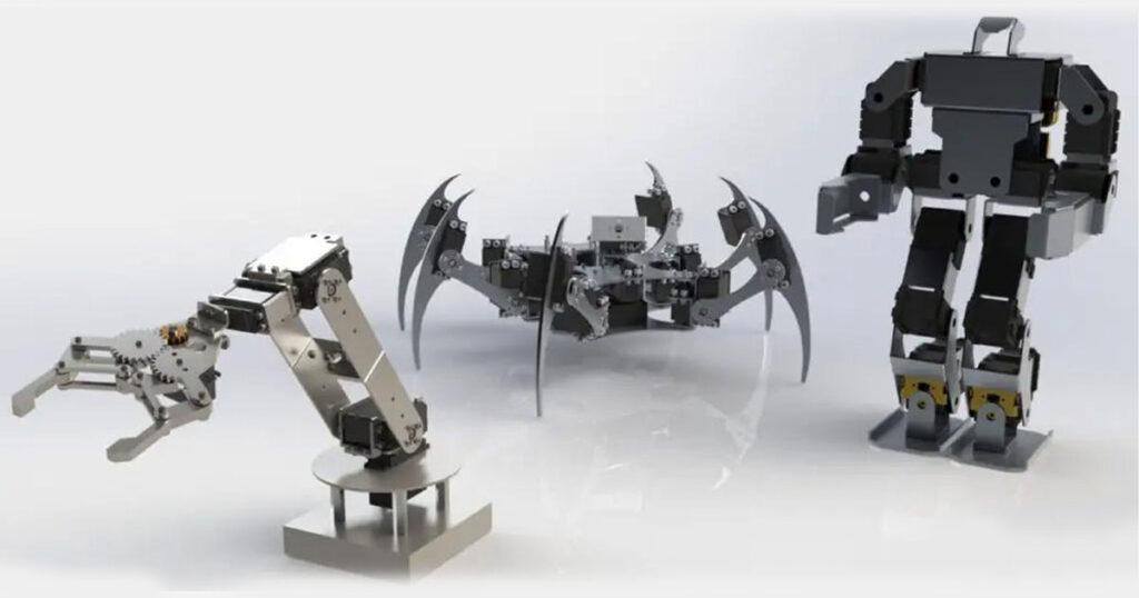
In industrial type servo motors the position feedback sensor is usually a high precision encoder, while in the smaller RC or hobby servos the position sensor is usually a simple potentiometer. The actual position captured by these devices is fed back to the error detector where it is compared to the target position. Then according to the error the controller corrects the actual position of the motor to match with the target position.Hobby servos are small in size actuators used for controlling RC toys cars, boats, airplanes etc. They are also used by engineering students for prototyping in robotics, creating robotic arms, biologically inspired robots, humanoid robots and so on.In industrial type servo motors the position feedback sensor is usually a high precision encoder, while in the smaller RC or hobby servos the position sensor is usually a simple potentiometer. The actual position captured by these devices is fed back to the error detector where it is compared to the target position. Then according to the error the controller corrects the actual position of the motor to match with the target position.
How Servo Motors Work?
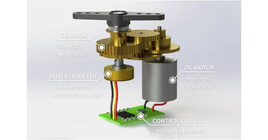
There are four main components inside of a hobby servo, a DC motor, a gearbox, a potentiometer and a control circuit. The DC motor is high speed and low torque but the gearbox reduces the speed to around 60 RPM and at the same time increases the torque.

The potentiometer is attached on the final gear or the output shaft, so as the motor rotates the potentiometer rotates as well, thus producing a voltage that is related to the absolute angle of the output shaft. In the control circuit, this potentiometer voltage is compared to the voltage coming from the signal line. If needed, the controller activates an integrated H-Bridge which enables the motor to rotate in either direction until the two signals reach a difference of zero.
A servo motor is controlled by sending a series of pulses through the signal line. The frequency of the control signal should be 50Hz or a pulse should occur every 20ms. The width of pulse determines angular position of the servo and these type of servos can usually rotate 180 degrees (they have a physical limits of travel).
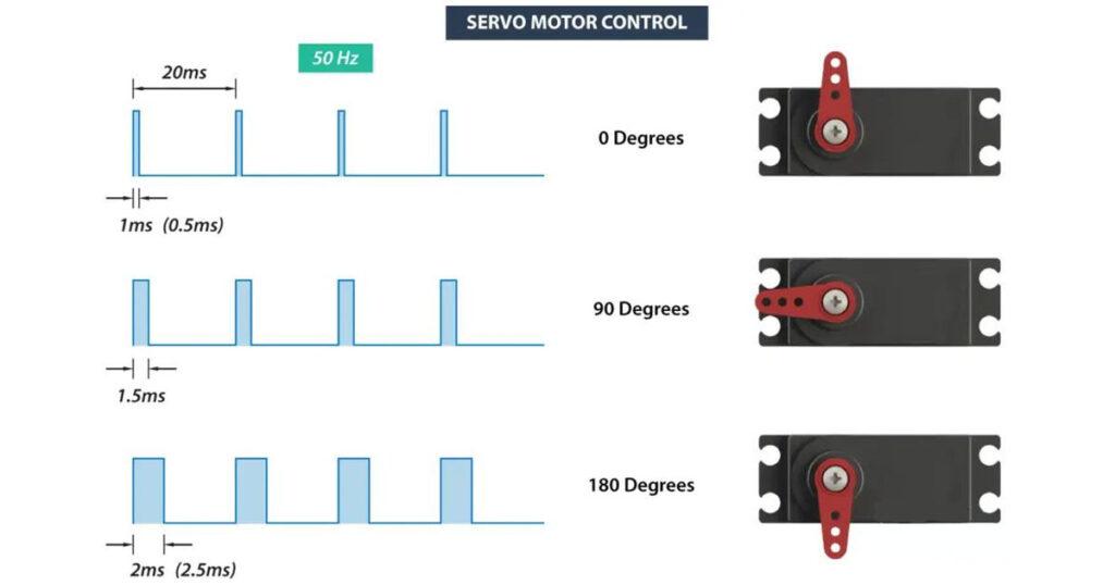
Generally pulses with 1ms duration correspond to 0 degrees position, 1.5ms duration to 90 degrees and 2ms to 180 degrees. Though the minimum and maximum duration of the pulses can sometimes vary with different brands and they can be 0.5ms for 0 degrees and 2.5ms for 180 degrees position.
Arduino Servo Motor Control
Let’s put the above said to test and make a practical example of controlling a hobby servo using Arduino. I will use the MG996R which is a high-torque servo featuring metal gearing with stall torque of 10 kg-cm. The high torque comes at a price and that’s the stall current of the servo which is 2.5A. The running current is from 500mA to 900mA and the operating voltage is from 4.8 to 7.2V.

The current ratings indicate that we cannot directly connect this servo to the Arduino, but we must use a separate power supply for it.
Circuit Diagram
Here’s the circuit diagram for this example.
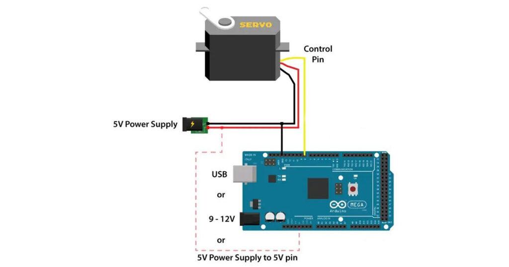
We simply need to connect the control pin of the servo to any digital pin of the Arduino board, connect the Ground and the positive wires to the external 5V power supply, and also connect the Arduino ground to the servo ground.
The S90 Micro Servo has lower current consumption, around 100-200mA no-load running current, but around 500-700mA stall current. On the other hand, the Arduino 5V pin can output only around 500mA if powered via USB, or up to 1A in powered via the barrel connector. Even though it’s possible to run these 9g servo motors directly to Arduino, for more stable work I would suggest to always use an external power supply for them.
Servo Motor Control Arduino Code
Now let’s take a look at the Arduino code for controlling the servo motor. The code is very simple. We just need to define the pin to which the servo is connect, define that pin as an output, and in the loop section generate pulses with the specific duration and frequency as we explained earlier.
#define servoPin 9

void setup() {
  pinMode(servoPin, OUTPUT);
}

void loop() {
   // A pulse each 20ms
    digitalWrite(servoPin, HIGH);
    delayMicroseconds(1450); // Duration of the pusle in microseconds
    digitalWrite(servoPin, LOW);
    delayMicroseconds(18550); // 20ms - duration of the pusle
    // Pulses duration: 600 - 0deg; 1450 - 90deg; 2300 - 180deg
}
After some testing I came up with the following values for the duration of the pulses that work with my servo. Pulses with 0.6ms duration corresponded to 0 degrees position, 1.45ms to 90 degrees and 2.3ms to 180 degrees.
Nevertheless, let’s take a look at a more convenient way of controlling servos using Arduino. That’s using the Arduino servo library.
#include <Servo.h>

Servo myservo;  // create servo object to control a servo

void setup() {
  myservo.attach(9,600,2300);  // (pin, min, max)
}

void loop() {
  myservo.write(0);  // tell servo to go to a particular angle
  delay(1000);

  myservo.write(90);
  delay(500);

  myservo.write(135);
  delay(500);

  myservo.write(180);
  delay(1500);
}
Here we just need to include the library, define the servo object, and using the attach() function define the pin to which the servo is connected as well as define the minimum and maximum values of the pulses durations. Then using the write() function we simply set the position of the servo from 0 to 180 degrees.