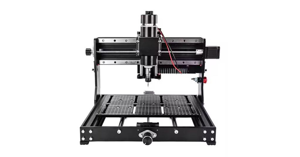
3020 CNC Machine
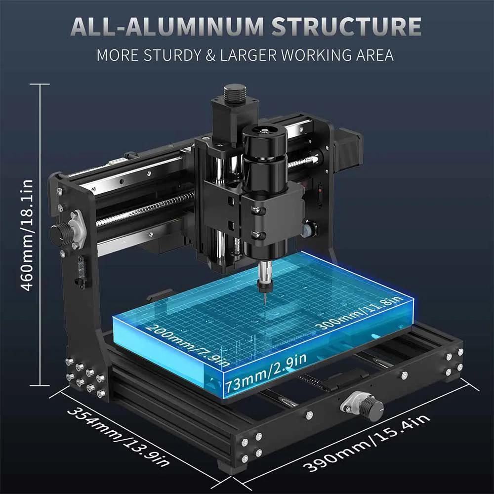
The 3020 CNC machine compact computer numerical control milling and engraving machine designed for precision control milling, cutting on various material. The “3020” refers to its working area dimensions 300mm (X-axis) × 200mm (Y-axis) making it suitable for small workshop and light industrial applications.
Key features of the 3020 CNC machine:
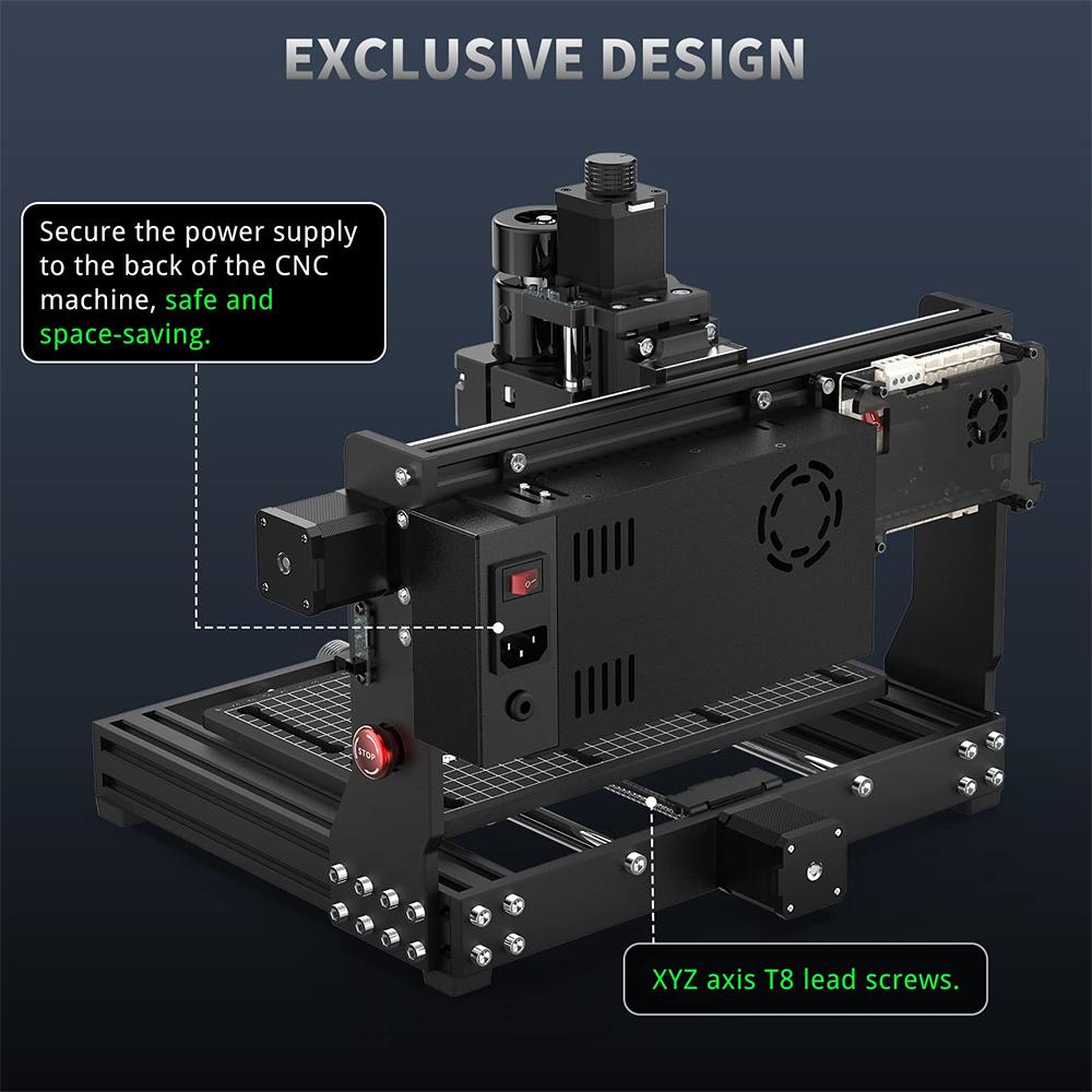
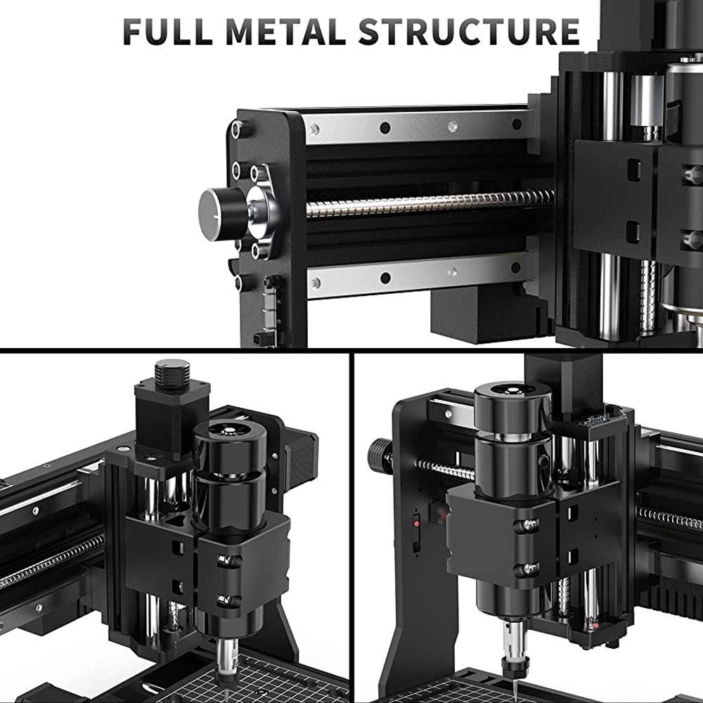
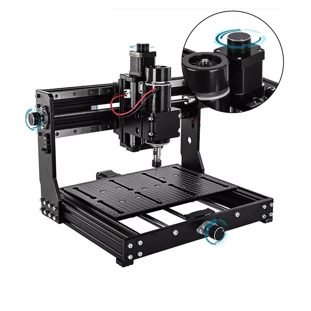
Frame Material: Use aluminium alloy for durability.
Work Area: 300mm x 200mm (3020), suitable for small projects.
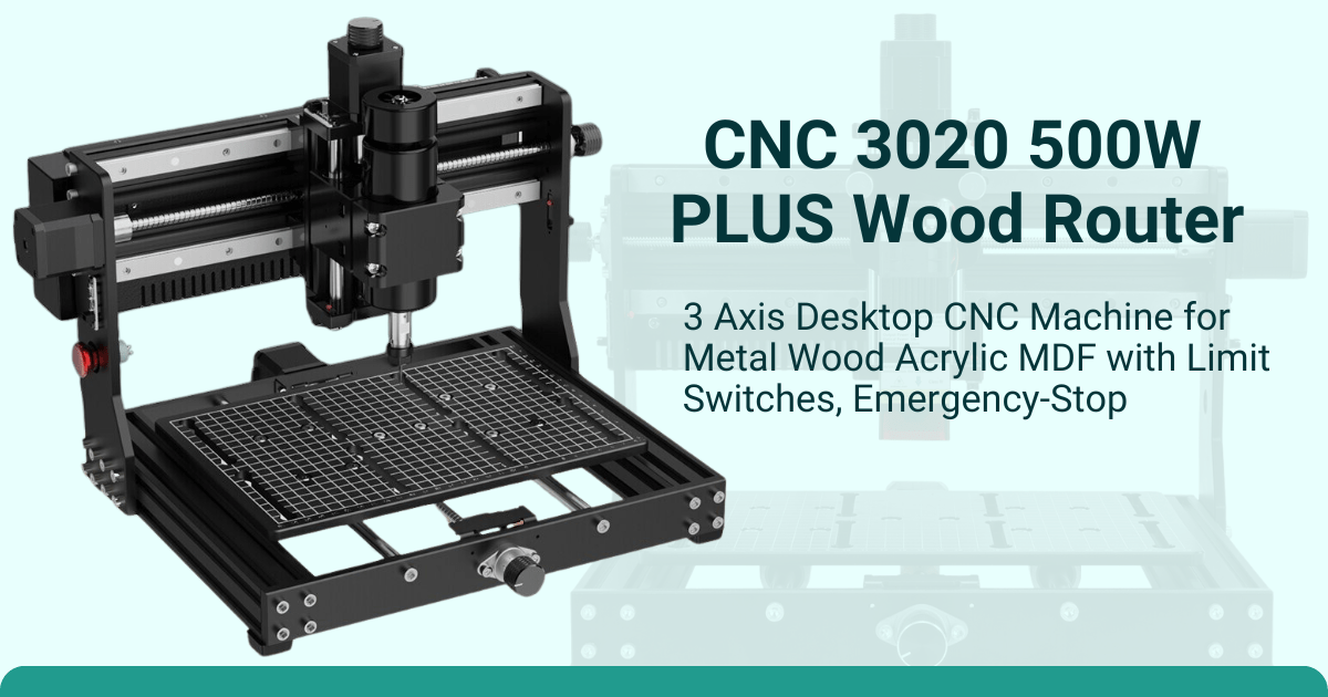
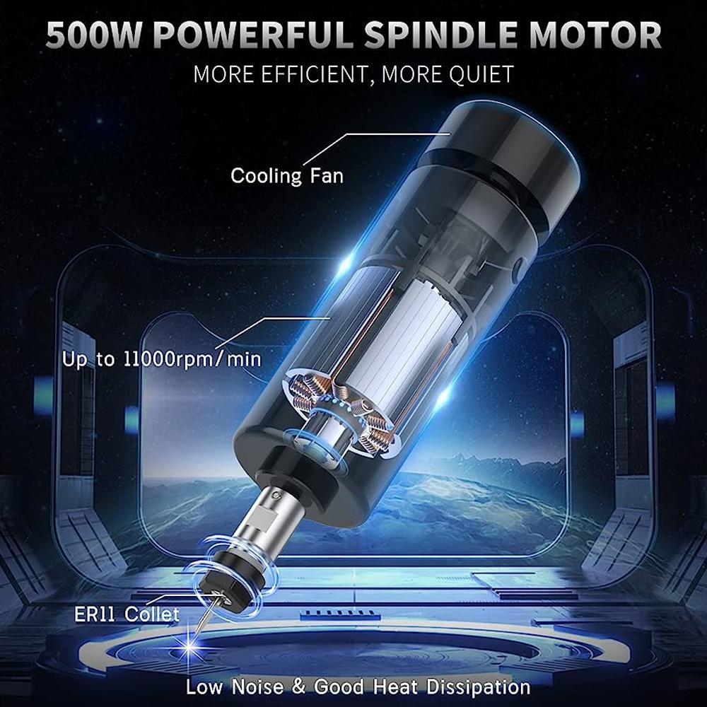
Spindle Power: Typically ranges from 200W to 500W, depending on the model.
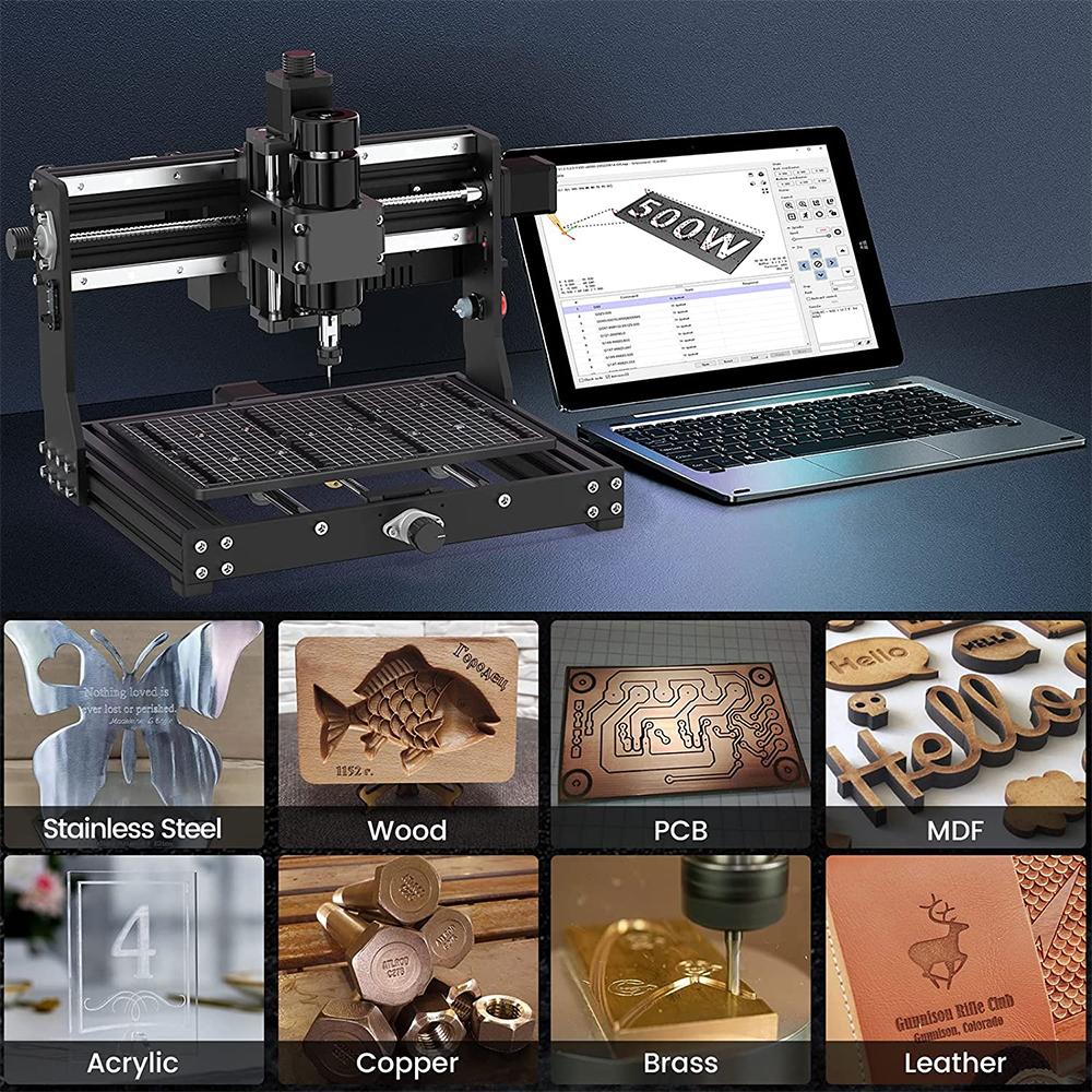
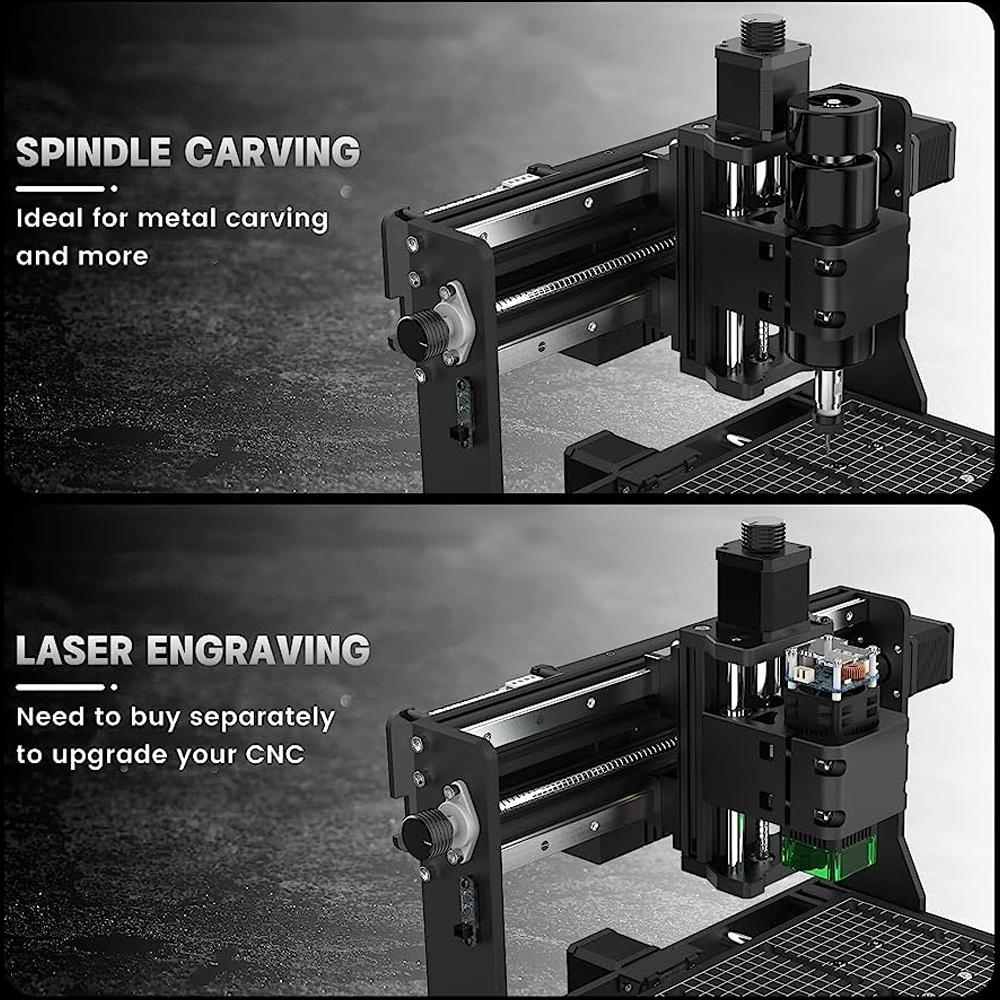
Speed Range: Variable speed from 8,000 to 24,000 RPM Material Compatibility: Can cut wood, acrylic, PCB, aluminium, brass, and some soft metals.
Why Choose a 3020 CNC Machine Over Other CNC Machines:
This CNC machine is a cost-effective solution, offering advanced features at a fraction of the price of industrial CNCs. Its design requires minimal maintenance compared to larger machines, making it a hassle-free choice for users. With versatile material compatibility, it works seamlessly with wood, plastic, acrylic, PCB, and soft metals, catering to various project needs. The sturdy aluminum frame enhances stability and precision by reducing vibrations, ensuring accurate results every time. Its compact, space-saving design is perfect for home workshops or small businesses, while its lightweight and portable build allows for easy relocation and convenience.
Setup for 3020 machines:
Setting up a 3020 CNC machine requires careful preparation and attention to detail to ensure optimal performance. This guide provides a comprehensive walkthrough for assembling and configuring your machine:
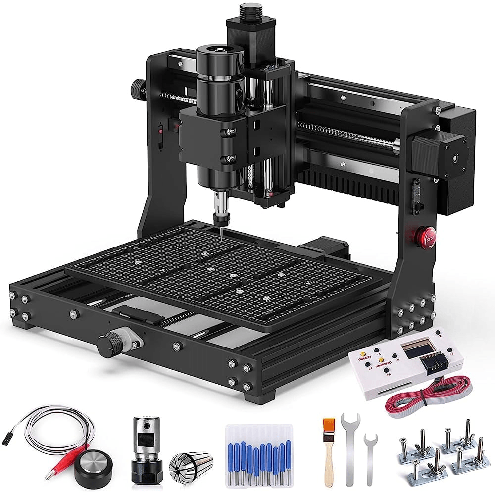
1. Unboxing and Inspecting Components
- Unpack Carefully: Remove all parts from the packaging and check against the parts list provided in the manual. Ensure you have all components, such as the frame, motors, controller, spindle, and cables.
- Inspect for Damage: Check for any signs of shipping damage, especially on the frame, motors, and electronics.
- Organize Tools and Parts: Arrange all tools (screwdrivers, Allen keys, wrenches) and machine parts in an accessible manner to streamline the assembly process.
2. Assembling the Frame
- Connect the Base: Securely attach the aluminum frame pieces using the provided screws and brackets. Ensure the base is square and level to maintain machine accuracy.
- Install Rails and Carriages: Attach linear rails and carriage blocks to the frame. Align them properly to minimize binding during movement.
- Mount the Gantry: Position and attach the gantry (X-axis frame) to the base. Ensure all bolts are tightened but avoid overtightening to prevent deformation.
3. Installing Motors and Belts
- Mount Stepper Motors: Attach the stepper motors to their designated positions on the X, Y, and Z axes. Secure them firmly to prevent vibrations.
- Align Belts or Lead Screws: If your 3020 uses belts, ensure they are properly tensioned and aligned. For lead screws, check for straightness and ensure smooth movement.
- Connect Couplers: Attach motor shafts to the lead screws or pulleys using couplers. Verify there is no slippage or misalignment.
4. Installing the Spindle
- Mount the Spindle Holder: Attach the spindle holder to the Z-axis carriage. Double-check that it is securely fastened.
- Insert the Spindle: Slide the spindle into the holder and tighten the clamps. Ensure the spindle is aligned vertically.
- Connect Spindle Power: Attach the spindle’s power cable to the controller, following the manual’s wiring diagram.
5. Connecting Electronics
- Wire the Motors: Connect the stepper motor cables to the corresponding ports on the controller box. Ensure cables are routed neatly to avoid interference.
- Attach Limit Switches: If your machine includes limit switches, install them at the ends of each axis and connect them to the controller.
- Connect the Controller: Plug the controller box into a power source and connect it to your computer via USB or the appropriate interface.
6. Configuring Software
- Install CNC Software: Download and install the recommended software, such as GRBL Control (Candle), Mach3, or another compatible program.
- Configure Settings: Input the machine parameters, such as stepper motor steps per millimeter, feed rates, and travel limits, into the software. Refer to the user manual for specific values.
- Test Axis Movement: Use the software to jog each axis, ensuring smooth and accurate movement. Check for any unusual noises or resistance.
7. Calibration and Fine-Tuning
- Square the Machine: Use a square tool to ensure the gantry is perpendicular to the base.
- Level the Bed: Adjust the bed or install a spoil board to create a flat working surface.
- Calibrate Steps per Millimeter: Perform a calibration test to verify that each axis moves the correct distance when commanded.
- Set Spindle Speeds: Adjust spindle RPM settings based on the material you plan to machine.
8. Testing the Machine
- Secure the Material: Clamp a piece of scrap material to the bed for a test run.
- Run a Test File: Load a simple G-code file into the software and monitor the machine as it executes the program.
- Inspect Results: Check the test piece for accuracy, surface finish, and any signs of misalignment.
9. Maintenance Tips
- Check Tightness Regularly: Periodically check and tighten screws, belts, and couplers.
- Lubricate Moving Parts: Apply lubricant to lead screws, linear rails, and other moving parts to reduce wear.
- Clean the Machine: Remove dust and debris after each use to maintain optimal performance.
Application for 3020 CNC machine: